DSK MFG Series Geared Motors: Models, Specifications, and Selection Guide
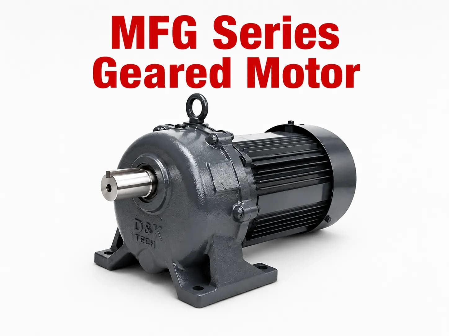
The DSK MFG Series is a line of parallel-shaft helical geared motors from Daesung Korea, featuring power ratings from 0.2 to 7.5 kW and gear ratios from 1/5 to 1/200. Available in foot-mounted (MFG) and flange-mounted (MFGV) configurations with optional brakes, this article covers the construction, specifications, decoding, model list, technical drawings, and selection guidelines.
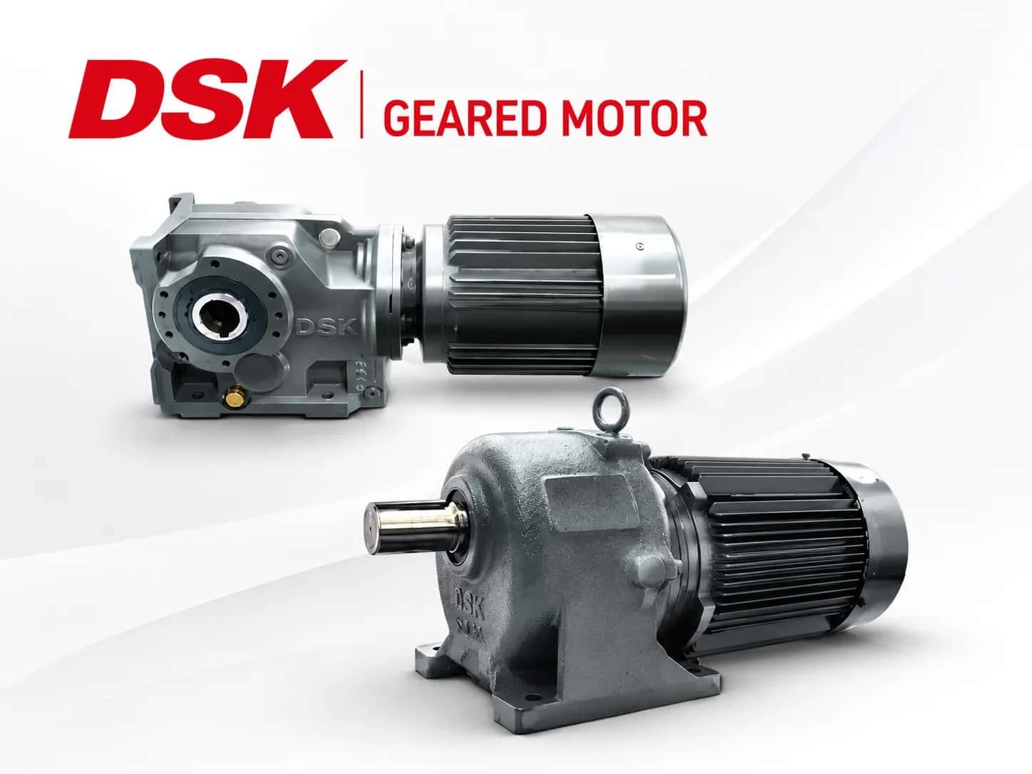
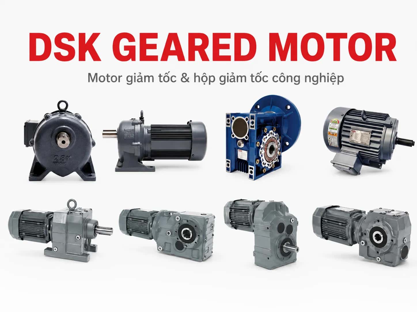
DSK GEARED MOTOR

MFG SERIES
General Introduction
In modern conveyor systems, mixing equipment, lifting mechanisms, and industrial automation lines, geared motors play a core role in regulating speed and increasing output torque. The DSK MFG Series (researched, manufactured, and developed by the renowned industrial group Daesung Industrial Co., Ltd. – South Korea) is one of the leading optimal parallel shaft drive solutions.
With a history of extensive technical cooperation with major Japanese names such as SEIKI Co., Ltd (1986) and especially SKK Co., Ltd (1990), Daesung Industrial Co., Ltd has perfected the localization process and upgraded DSK geared motor manufacturing technology to global standards. By applying advanced CNC Skiving (Hobbing) gear profile machining technology for the first time in the domestic manufacturing industry in 1995, the gear surfaces of the MFG series achieve absolute mechanical precision, eliminate noise, and optimize transmission efficiency.
This article will provide mechanical engineers, procurement specialists, and manufacturing enterprises with the most comprehensive, intuitive, and detailed overview of technical specifications, mechanical calculation formulas, and accurate model selection procedures for the DSK MFG Series geared motors.
What is the DSK MFG Series?
The DSK MFG Series is a line of parallel shaft geared motors designed and manufactured by the Machinery Division of Daesung Industrial Co., Ltd., South Korea. The product is manufactured based on the complete inheritance of the technical specifications, structural geometric dimensions, and operational quality from the renowned Japanese brand SKK.
This gearbox utilizes a helical gear transmission mechanism tiered from 2-stage reduction (Double Reduction - denoted as D) to 3-stage reduction (Triple Reduction - denoted as T). The geometric design of the MFG series allows for direct replacement installation into the position of any SKK reduction equipment currently operating on production lines without the need to modify foundations or mechanical connection structures.
The product line has achieved all rigorous international technical standard certifications, including the European quality system certification CE Mark (in 2004) and the mandatory Chinese safety certification CCC Mark (in 2005).
Key Features of DSK MFG Series
Based on the original technical documentation from the manufacturer Daesung, the DSK MFG Series gear motor line possesses many outstanding characteristics:
Versatile Type, Wide Speed Reduction Ratio: The MFG series meets all diverse industrial application requirements thanks to an extremely wide range of reduction ratios, spanning from $1/5$ to $1/200$, allowing for precise adjustment of the output speed range according to the technological requirements of the actuator.
Compact, Lightweight but Great Power: By calculating the optimal stress balance between machine components, the manufacturer has eliminated excess mass from the gearbox housing. The result is a drive unit with a streamlined geometric size and lightweight construction, yet with extremely powerful torque-bearing capacity.
High Efficiency, Low Noise, Quiet Operation: To achieve ultra-quiet operation and minimize vibration, DSK engineers conducted in-depth analysis of the causes of acoustic waves within the gearbox chamber. The machining precision of the Pinion and Gear teeth has been enhanced to near-ideal levels, ensuring maximum transmission efficiency and reducing energy loss due to friction.
Advanced Seals System: To completely prevent lubricant leakage, the MFG gear motor utilizes an Oil Seal structure at both the Output Shaft and the Motor Side. Simultaneously, the mating surfaces between the Gear Case and the motor Bracket are completely sealed with heavy-duty O-ring rubber gaskets.
Universal Installation & Maintenance Free: The entire MFG Series product range employs a factory-packed high-pressure grease lubrication method (Grease Packed). This feature allows users to freely install the equipment at any angle or orientation in space without concerns regarding oil levels. Furthermore, the maintenance-free operating cycle is significantly extended.
Perfect Interchangeability with SKK: This is a strategic advantage for older factories using Japanese equipment. The mounting dimensions of the DSK MFG series are completely identical to the corresponding SKK gear reducers, helping to shorten downtime during replacement and repair.
DSK MFG Series Construction
The cutaway view of the DSK MFG Series parallel gear reducer demonstrates the seamless integration of high-precision mechanical components:

Integrated Motor: Utilizes a specialized motor generation for reduction mechanisms, incorporating Class F insulation materials with high thermal overload mechanical properties, ensuring optimal energy efficiency for the entire system.
Gear Case: The housing and cover are designed with an extremely rigid Monobloc type structure (front case and gear case in one piece). Areas subjected to high external forces and torque are reinforced with thickened supports (Reinforced foot) to eliminate deformation or housing cracks under shock loads.
Gearing Section:
First Pinion: Machined directly or fixed onto the input motor shaft.
First Gear: Receives motion from the First Pinion to perform the first reduction stage.
Second Pinion: Coaxial with the First Gear, transmitting motion to the next stage.
Second Gear: Performs the second reduction stage.
Third Pinion: Used on high gear ratio models (Triple Reduction).
Third Gear: The largest gear, directly connected to the output shaft to transmit maximum torque.
Bearing System: At critical positions such as intermediate shafts and high-load low-speed output shafts, cylinder bearings are applied to maintain radial load capacity. Auxiliary guide positions utilize highly reliable DX-metal slip-ring bushings.
Operating Principle
When power is supplied to the motor, the rotor shaft rotates at high speed, transmitting kinetic energy to the first-stage pinion (First Pinion). Through the sequential meshing gear pairs (First Gear => Second Pinion => Second Gear => Third Pinion => Third Gear), the angular velocity decreases inversely proportional to the number of teeth in each meshing pair. The reduction in angular velocity at the output (Output Rpm) simultaneously increases the dynamic driving torque according to the law of conservation of mechanical energy, providing stable, high pulling force at the output shaft.
DSK MFG Series Technical Specifications
Below is a summary table of the basic operating technical specifications for the 4-pole gear motor series, at 60Hz frequency, standardized according to the original DSK catalog documentation:
Motor Power (kW) | Nominal Gear Ratio | Reducer Frame | Rated Output Speed (rpm) | Actual Ratio | Allowable Output Torque (kgf⋅m) | Allowable OHL (kgf) |
0.2 kW | 1/5 | 518 D | 360 | 4.980 | 0.49 | 30 |
1/10 | 518 D | 180 | 10.045 | 0.99 | 60 | |
1/20 | 518 D | 90 | 19.429 | 1.9 | 150 | |
1/30 | 522 D | 60 | 28.848 | 2.9 | 170 | |
1/60 | 522 T | 30 | 56.478 | 5.8 | 180 | |
1/150 | 524 T | 10 | 148.500 | 14.9 | 350 | |
0.4 kW | 1/5 | 22 D | 360 | 5.060 | 1.1 | 90 |
1/10 | 22 D | 180 | 9.915 | 2.0 | 150 | |
1/30 | 24 D | 60 | 28.848 | 5.8 | 303 | |
1/60 | 24 T | 30 | 59.925 | 11.8 | 350 | |
1/130 | 32 T | 11.5 | 131.423 | 26.3 | 470 | |
1/200 | 38 T | 7.5 | 198.731 | 48.1 | 679 | |
0.75 kW | 1/10 | 24 D | 180 | 10.245 | 3.8 | 218 |
1/30 | 32 D | 60 | 29.049 | 10.9 | 470 | |
1/60 | 32 T | 25 | 59.918 | 22.5 | 470 | |
1/130 | 38 T | 11.5 | 131.045 | 49.2 | 679 | |
1/200 | 42 T | 7.5 | 197.976 | 74.4 | 950 | |
1.5 kW | 1/10 | 32 D | 150 | 10.255 | 7.7 | 265 |
1/30 | 38 D | 50 | 29.591 | 26.8 | 610 | |
1/60 | 38 T | 25 | 57.224 | 43.0 | 679 | |
1/100 | 42 T | 15 | 101.510 | 80.1 | 950 | |
1/200 | 56 T | 7.5 | 198.000 | 155 | 1700 | |
2.2 kW | 1/10 | 38 D | 180 | 10.079 | 11.1 | 435 |
1/30 | 42 D | 60 | 29.157 | 32.1 | 806 | |
1/50 | 42 T | 30 | 48.206 | 64.1 | 902 | |
1/100 | 48 T | 15 | 102.857 | 115 | 1400 | |
1/200 | 63 T | 7.5 | 198.677 | 219 | 2000 | |
3.7 kW | 1/10 | 42 D | 150 | 10.183 | 18.9 | 556 |
1/30 | 48 D | 60 | 28.875 | 53.5 | 1118 | |
1/60 | 48 T | 25 | 60.594 | 104 | 1400 | |
1/100 | 56 T | 15 | 99.125 | 162 | 1700 | |
5.5 kW | 1/10 | 42 D | 180 | 9.755 | 26.9 | 499 |
1/30 | 56 D | 50 | 28.875 | 79.6 | 1529 | |
1/60 | 56 T | 25 | 57.476 | 158 | 1700 | |
1/100 | 63 T | 15 | 98.825 | 247 | 2000 | |
7.5 kW | 1/5 | 48 D | 360 | 4.962 | 18.6 | 223 |
1/10 | 48 D | 150 | 9.933 | 37.3 | 620 | |
1/30 | 63 D | 50 | 28.988 | 109 | 1634 | |
1/80 | 63 T | 25 | 58.154 | 214 | 2000 |
Important manufacturer note: The output shaft speed is based on the motor's synchronous speed multiplied by the nominal gear ratio. The Allowable Overhung Load (OHL) value is calculated precisely at the center position of the exposed shaft section. Some product codes in the table feature a torque-limiting design to protect the helical gear system; users should consult the protection specifications of each series when operating under heavy loads.
DSK MFG Series model code reading rules
To accurately configure the equipment according to the technical documentation from Daesung Industrial Co., Ltd., the product identifier is structured according to the standardized diagram below:

Detailed analysis of a practical example: MFG B 24 T - 60R S 0.4 - 4
MFG: Abbreviation for the Parallel Shaft Geared Motor Series.
B (Brake / Mounting Type): *
Space: Standard Foot Mount type.B: Integrated safety electromagnetic brake system (Brake).V: Shaped output Flange Mount structure.
24 (Frame Size / Shaft Diameter): Indicates the nominal size of the gearbox housing frame and the outer diameter of the output shaft.
T (Reduction Stage):
D: 2-stage helical gear reduction mechanism (Double Reduction).T: 3-stage helical gear reduction mechanism (Triple Reduction).
60R (Reduction Ratio): Symbol indicating the nominal reduction ratio (e.g., in this case, a $1/60$ reduction).
S (Motor Series): Manufacturer brand of the integrated electric motor rotor and stator core:
S: Motor series supplied by Shinkang.H: Motor series manufactured by Higen.
0.4 (Motor Capacity): Rated mechanical power of the motor (0.4 corresponds to $0.4 ext{ kW}$).
4 (Motor Pole): Number of magnetic poles of the motor winding (4 indicates a 4-pole motor).
Models in the MFG Series
The DSK catalog provides detailed technical drawings and weight specifications for each specific model:
Foot Mount Geared Motor - MFG Series
0.2 kW power range: MFG 518D-5,10,20 RS 0.2-4 (Weight: 6.5 kg); MFG 522D-30 RS 0.2-4 (Weight: 7.0 kg); MFG 522T-50,60,100 RS 0.2-4 (Weight: 7.4 kg); MFG 524T-150,200 RS 0.2-4 (Weight: 9.6 kg).
0.4 kW power range: MFG 220-5,15 RS 0.4-4 (Weight: 13.5 kg); MFG 24D-30 RS 0.4-4 (Weight: 14.5 kg); MFG 24T-45,50,60,75 RS 0.4-4 (Weight: 15.5 kg); MFG 32T-100,130,150 RS 0.4-4 (Weight: 24.5 kg); MFG 38T-200 RS 0.4-4 (Weight: 34 kg).
0.75 kW power range: MFG 240-5,10,15,20 RS 0.75-4 (Weight: 19.5 kg); MFG 320-30 RS 0.75-4 (Weight: 28.5 kg); MFG 32T-45,50,60,75 RS 0.75-4 (Weight: 29.5 kg); MFG 38T-130,150 RS 0.75-4 (Weight: 38.5 kg); MFG 42T-200 RS 0.75-4 (Weight: 50.5 kg).
1.5 kW power range: MFG 320-5,10,15,20 RS 1.5-4 (Weight: 37.4 kg); MFG 38D-30 RS 1.5-4 (Weight: 45.4 kg); MFG 38T-45,50,60,75 RS 1.5-4 (Weight: 48.4 kg); MFG 42T-100 RS 1.5-4 (Weight: 60.4 kg); MFG 48T-130,150 RS 1.5-4 (Weight: 76.4 kg); MFG 56T-200 RS 1.5-4 (Weight: 95.4 kg).
2.2 kW power range: MFG 38D-5,10,15,20 RS 2.2-4 (Weight: 53.2 kg); MFG 42D-30 RS 2.2-4 (Weight: 63.7 kg); MFG 42T-50,60 RS 2.2-4 (Weight: 64.7 kg); MFG 48T-75,100 RS 2.2-4 (Weight: 83.2 kg); MFG 56T-130 RS 2.2-4 (Weight: 103.2 kg); MFG 63T-200 RS 2.2-4 (Weight: 126.2 kg).
3.7 kW power range: MFG 42D-5,10,15,20 RS 3.7-4 (Weight: 68.6 kg); MFG 48D-30 RS 3.7-4 (Weight: 85.6 kg); MFG 48T-50,60 RS 3.7-4 (Weight: 90.6 kg); MFG 56T-75,100 RS 3.7-4 (Weight: 77.6 kg); MFG 63T-130,150 RS 3.7-4 (Weight: 131.6 kg).
5.5 kW power range: MFG 42D-5,10,15 RS 5.5-4 (Weight: 89.9 kg); MFG 48D-20 RS 5.5-4 (Weight: 112.9 kg); MFG 56D-30 RS 5.5-4 (Weight: 131.9 kg); MFG 56T-45,50,60 RS 5.5-4 (Weight: 138.9 kg); MFG 63T-75,100 RS 5.5-4 (Weight: 165.9 kg).
7.5 kW power range: MFG 48D-5,10,15 RS 7.5-4 (Weight: 92.5 kg); MFG 56D-20 RS 7.5-4 (Weight: 149.5 kg); MFG 63D-30 RS 7.5-4 (Weight: 171.5 kg); MFG 63T-45,50 RS 7.5-4 (Weight: 182.5 kg).
Flange Mount Geared Motor - MFGV Series
The flange mount series features the same power ranges and reduction gear frame sizes but is optimized with a locating flange housing at the output shaft end:
Typical examples: MFGV 518D-5,10,15,20 RS 0.2-4 (Weight: 6.6 kg); MFGV 522D-30 RS 0.2-4 (Weight: 7.4 kg); MFGV 240-30 RS 0.4-4 (Weight: 15.5 kg); MFGV 32T-45,50,60,75 RS 0.75-4 (Weight: 31.5 kg); MFGV 32D-5,15 RS 1.5-4 (Weight: 38.4 kg); MFGV 42D-30 RS 2.2-4 (Weight: 64.2 kg); MFGV 42D-5,10,15,20 RS 3.7-4 (Weight: 69.6 kg)...
DSK MFG Series Gearbox Mounting Types
The manufacturer provides three precise physical mounting configuration options:
1. Foot Mount Type
Features a reinforced, cast-integrated foot base at the bottom of the gearbox housing. This is the most common mounting style, secured by 4 bolts fixed onto a flat machine frame.
2. Flange Mount Type (Designated V)
The output gearbox housing is integrated with a circular positioning flange featuring load-bearing threads (MY Taps oriented throughout). Suitable for vertical mounting structures or direct connection to the walls of agitators or extruders.
3. Electromagnetic Brake Integration Option (Designated B / Brake Motor)
Used for mechanisms requiring immediate forced stopping or shaft locking during power failure. The braking system is divided into two core technology lines:
SHB AC-B Type Brake Series: Utilizes AC power connected in parallel directly to the main motor terminal box (no auxiliary rectifier circuit required). The brake operates mechanically via a high-pressure spring system, ensuring extreme safety during power loss incidents. The Dry Multi-plate design generates high braking torque and allows for simple gap adjustment.
SHB DC-B Type Brake Series: Utilizes a single or multi-plate brake mechanism operated by DC current via a rectifier power unit. The compact geometric dimensions are suitable for tight spaces, and the mechanical gap is fine-tuned directly via a locking nut system.
Genuine DSK Rectifier Circuit[cite: 1795]:
- SH-10 Series: Input AC 220V (50/60Hz) ---> Output DC 90V [cite: 1799]
- SH-20 Series: Input AC 440V (50/60Hz) ---> Output DC 190V [cite: 1799]
Practical Applications
Based on the load classification table (Table 2 Driven Machine) from Daesung technical documentation, the MFG series is engineered for optimal compatibility with the following industrial machinery assemblies:
Conveyor Systems: Stable operation for both uniform load conveyors (symbol U), such as packaging and light food conveyors, and non-uniform load systems (symbol M) with fluctuating load current.
Cranes, Hoists & Elevators: Integrates with SHB AC/DC safety anti-slip brakes specifically for hoisting mechanisms, automated material hoists, freight elevators, or smart parking systems.
Ceramic and Construction Material Machinery: Capable of withstanding heavy impact shock loads (symbol H) in feeding mechanisms, crushers, and hammer mills.
Mixers & Water Treatment Equipment: Features a double seal design to prevent water and dust ingress into the helical gear chamber, suitable for wastewater treatment systems and continuous flow sedimentation tanks.
Machine Tools and Paper Machines: Ensures high operational angular precision and minimal vibration for main drive shafts in cutting and machining mechanisms.
Selection Procedure and Guidelines for DSK MFG Geared Motors
To ensure equipment longevity and prevent output shaft failure due to overloading or incorrect inertia coefficient calculations, engineers must follow the manufacturer's standard 7-step procedure as follows:
Step 1: Determine the required power and output speed
Clearly define the output rotation speed (rpm) and power (kW) required for your machinery to operate.
Step 2: Select the nominal gear ratio
Divide the motor rotation speed by the required output speed to select the closest gear ratio available in the catalog specification table.
Step 3: Look up the service factor based on load characteristics (Sf1)
Select the appropriate service factor Sf1 based on daily operating hours and load type:
Operating under 3 hours/day: Uniform load = 1.0; Moderate shock load = 1.0.
Operating from 3 to 10 hours/day: Uniform load = 1.0; Moderate shock load = 1.25.
Operating over 10 hours/day: Moderate shock load = 1.25; Heavy shock load = 1.5.
Step 4: Determine the start-stop frequency factor (Sf2)
If your machinery requires frequent start-stop cycles per hour, the inertial force will be significant.
Refer to Table 4 in the catalog to find the Sf2 factor based on the number of starts per hour and the load inertia ratio.
Step 5: Calculate the required total torque (T)
Apply the standard traction force calculation formula: T = Te x Sf1 x Sf2 (Where Te is the actual operating torque of the machine).
Step 6: Select the appropriate Frame size and Model
Use the total torque (T) value calculated in Step 5 to cross-reference with the "Permissible Torque" column in the catalog specification table.
It is mandatory to select a Model with a permissible torque value greater than or equal to the actual T value you just calculated.
Step 7: Check the Overhung Load (OHL)
If you connect the output shaft using sprockets, gears, or belts (instead of direct coupling), calculate the force acting on the shaft neck using the formula: OHL = (2000 x Te x Sf1 x Sf2 / D) x (Cf / Lf) (Where: D is the pitch diameter of the sprocket/pulley, Cf is the transmission type factor, Lf is the load position factor on the shaft).
Ensure that this actual OHL value is smaller than the permissible OHL value of that Model in the catalog lookup table.
Troubleshooting
The standardized operational troubleshooting procedure table, translated directly from DSK's technical documentation, helps engineers quickly isolate the cause of failure:
1. Main Motor System Faults
Fault Symptom | Potential Root Cause | Technical Troubleshooting Procedure |
Powered but shaft does not rotate (No-load state) | * Loss of power supply or broken power cable. * Contactor contacts (switching device) burnt/damaged. * Broken stator winding inside the motor. | * Check voltage at motor terminals. * Measure winding resistance and housing insulation. * Replace faulty switching device. |
Loud humming noise, current spikes but fails to start | * Sudden phase loss in the 3-phase power system. * Mechanical mechanism or external load is jammed. | * Measure current and voltage of all 3 phases. * Disconnect mechanical load to isolate and check lubrication. |
Motor runs normally but output shaft does not rotate | * Key connecting the output shaft and sprocket/pulley is broken or has fallen out. | * Inspect external shaft mechanical coupling, reinstall new key according to technical specifications. |
Abnormally high housing temperature, smoking, or burning smell | * Continuous overload operation relative to rated power. * Supply grid voltage is too high or too low. * Cooling fins or motor tail fan clogged with dirt, blocking airflow. | * Reduce load to specified level or upgrade gearbox capacity. * Clean the motor tail cooling fan thoroughly. |
2. Specific Faults of Brake Geared Motors
Fault Symptom | Potential Root Cause | Technical Troubleshooting Procedure |
Brake does not release (Brake failure) | * Open circuit in the electromagnetic brake coil. * Defect of D.C Source (Rectifier unit). * Brake gap is too large, exceeding the electromagnetic pull-in range. | * Check continuity of the brake control cable. * Replace the brake rectifier unit. * Measure and readjust the mechanical brake gap using the dedicated adjustment nuts. |
Weak braking force, prolonged braking time | * Oil, grease, or industrial dust contamination on the inner disc surface. * Brake disc is worn or deformed. * Load inertia $GD^2$ exceeds the brake's design capacity. | * Remove the brake assembly and clean the brake pad surface using a specialized degreasing agent. * Replace with a new brake disc if wear exceeds the standard limit. |
FAQ — Frequently Asked Questions about DSK MFG Series
1. What is the replacement interval for Albania EP R00 grease for the MFG series in operating hours?
According to Daesung technical standards under normal factory operating conditions, Albania EP R00 grease (manufactured by Shell) or equivalent grease types must be completely drained and replaced every 20,000 hours of continuous operation.
2. What is the standard mechanical gap value for DSK electromagnetic brakes and how is it adjusted?
The gap value is specified according to the motor power range:
Motors from 0.4 kW to 3.7 kW: standard gap from 0.4 mm to 0.5 mm.
Motors from 5.5 kW to 37 kW: standard gap from 0.5 mm to 0.8 mm.
Adjustment method:
Remove the protective cover at the rear of the motor, use a feeler gauge to measure the distance between the armature and the stator of the electromagnetic brake. Then, tighten or loosen the gap adjustment nut until the standard value is reached as specified.
Adjustment method: Open the motor fan cover, use a feeler gauge to measure the distance between the armature and the stator of the brake, and rotate the gap adjustment nut until the standard parameter is achieved.
3. What is the frequency of periodic inspection for the electromagnetic brake system based on operating density?
DSK provides a mandatory inspection schedule based on the switching frequency of the equipment:
High-intensity operation (operating 2 or more times per minute): Periodic inspection after 60 days of operation.
Medium-intensity operation (operating less than 20 times within 30 minutes): Periodic inspection after 120 days of operation.
Low-intensity operation (operating less than 30 times within 1 hour): Periodic inspection after 180 days of operation.
4. Can the DSK MFG Series geared motor operate in extremely cold or excessively hot outdoor environments?
The MFG series is optimally designed to operate within an ambient temperature range strictly fluctuating from -20°C to 40°C. If the environment exceeds this temperature range, there is a risk of grease degradation or damage to the winding insulation.
5. What are the ambient humidity and installation altitude limits for the MFG series?
The gearbox operates safely at an ambient humidity below 100% (non-condensing state) and an installation altitude below 1,000 meters above sea level.
6. Why is an O-ring used at the mechanical interface between the motor flange and the gearbox housing instead of conventional liquid gasket?
Using a pressure-resistant molded O-ring optimizes the sealing effect, absolutely preventing lubricant leakage and protecting against water ingress from external pressure environments, thereby maintaining optimal lubrication.
7. What should be considered regarding the pitch circle diameter of the sprocket mounted on the output shaft of the MFG series?
To prevent shaft bending due to stress concentration, the pitch circle diameter of the sprocket or gear mounted on the output shaft must be selected to be greater than or equal to 3 times the outer diameter of the gearbox output shaft (3 x Output shaft diameter).
8. What is the technically correct position for the load application point on the protruding shaft of the MFG series?
The application point of the overhang load for the sprocket or drive gear must be pushed as close to the shaft shoulder as possible within the allowable range. Avoid installing the drive mechanism at the outer edge of the shaft, as this increases the bending moment, which can easily lead to mechanical fatigue and output shaft breakage.
9. What is the standard slack for the drive chain connected to the output shaft of the MFG series gearbox?
The safe mechanical slack (Amount of slack for chain) is strictly specified as 2% of the center distance between the two drive sprockets (Span distance - denoted as L). The formula for determining slack is: S = 0.02L. If the chain is too tight, it will damage the output shaft bearings; conversely, if the chain is too loose, it will generate extreme shock loads during startup, potentially breaking the gearbox teeth.
10. When installing a coupling flange onto the output shaft of the DSK MFG gearbox, what is the required machining tolerance range for the coupling flange bore?
To ensure perfect concentricity, the bore of the coupling mounted on the output shaft (or high-speed input shaft) must be precisely machined according to the standard fit tolerance range from h6/M6 to h6/P6. The manufacturer recommends slightly heating the coupling flange before pressing it onto the shaft to avoid impact forces that could damage the internal gearbox bearings.
11. What are the permissible tolerances for eccentricity and perpendicularity when installing a direct coupling for the MFG series?
When using a direct shaft connection method with a flexible coupling, the permissible perpendicularity tolerance between the mounting flange and the shaft centerline must not exceed 0.15mm T.I.R. Additionally, the concentricity deviation between the two connected shafts (concentricity error) must be within the defined limit of 0.15mm T.I.R.
12. What is the meaning of the gear code symbols "D" and "T" in models such as MFG 522D or MFG 32T?
D (Double reduction): Indicates a gearbox using a reduction drive structure consisting of 2 stages of helical gears in sequence, typically used for small and medium gear ratios.T (Triple reduction): Indicates a gearbox using a 3-stage helical gear reduction drive structure, specialized for generating very high gear ratios with ultra-slow output rotational speeds.
13. What is the special construction of the new generation "No-Noise Brake" series from DSK?
This is a proprietary design of the manufacturer (patent number 116289). By integrating an additional layer of specialized load-bearing elastic damping material (detailed part number 27) into the space between the brake lining disc (part number 28) and the fixed hub (part number 26). This structure completely eliminates metal impact noise and mechanical vibrations generated during the moment of continuous brake engagement and disengagement in automated logistics systems that require high quietness.
14. When applying the MFG series Geared Motor for vertical lifting mechanisms (Hoists, Cranes), how should the brake be selected?
For vertical lifting applications subject to direct gravitational force, it is mandatory to select a system with an extremely high brake safety factor. DSK recommends that the rated capacity of the electromagnetic brake assembly must be increased by one level higher than the actual capacity of the integrated electric motor. Specific example: For a motor using a 0.75kW 4P capacity, the electromagnetic brake system attached to the rear end must be selected with a torque size equivalent to the structure of a 1.5kW 4P motor series.
15. What technical advantages does the Class F insulation of the DSK MFG Series motor provide?
Class F insulation material allows the motor windings to withstand a limiting operating temperature of up to 155 degrees Celsius. This helps protect the motor safely against short-term overload incidents, high-amplitude repetitive starting currents, and significantly increases the lifespan of the windings compared to the older Class B materials in harsh factory operating environments.
Conclusion.
The DSK MFG Series geared motor from Daesung Industrial Co., Ltd. establishes itself as one of the parallel shaft gearmotors featuring high mechanical durability, a compact design, and a flexible torque range. The ability for universal mounting thanks to the Albania EP R00 sealed grease lubrication technology and 100% dimensional compatibility with the traditional SKK series make the MFG an excellent technical and economic solution.
Accurate calculation of the service factor based on the flywheel inertia GD^2 and strict adherence to the Overhung Load (OHL) limits are the keys to ensuring the long-term, reliable, and safe operation of your factory's drive systems.