Wintec WTM Series Electromagnetic Flowmeters: Construction and Installation
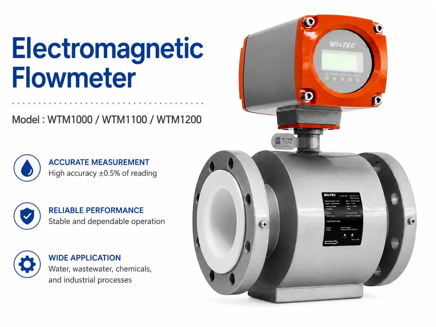
Discover the WTM electromagnetic flowmeter for measuring water, wastewater, chemicals, sludge, and pulp. Explore operating principles, material selection for liners and electrodes, sizing, installation, and wiring.
Wintec South Korea Electromagnetic Flowmeter WTM Series: Construction and Installation

Construction of the integrated WTM1000 electromagnetic flowmeter including converter, LCD display, detector, electrode, and lining.
WTM Electromagnetic Flowmeter – A stable flow measurement solution for water, wastewater, and industrial chemicals
In water treatment systems, wastewater, chemicals, sludge, alkaline solutions, acids, or industrial production lines, accurate flow measurement is a critical factor for operational control. One of the devices commonly used for these applications is the electromagnetic flowmeter.
The WTM electromagnetic flowmeter is a flow measurement device based on Faraday's law of electromagnetic induction. The device is suitable for conductive liquids, especially clean water, wastewater, industrial water, sludge, seawater, chemical solutions, alkaline solutions, acids, and types of liquids that do not contain oil or gas.
With models such as WTM1000, WTM1100, and WTM1200, this electromagnetic flowmeter series can meet various installation requirements, from integrated on-site types to remote types for harsh environments, high temperatures, vibrations, or locations that are difficult to observe.
1. What is an electromagnetic flowmeter?
An electromagnetic flowmeter is a device that measures liquid flow by applying Faraday's law of electromagnetic induction. When a conductive liquid passes through a magnetic field in the sensor body, an induced voltage is generated. This voltage is proportional to the flow velocity. The converter receives the signal from the electrodes, processes it, and converts it into a flow signal for display or transmission to the control system.
Output signals typically include:
4–20mA analog signal
Pulse signal
Optional RS232, RS422, or RS485 communication signals
Instantaneous flow value
Flow velocity value
Total accumulated flow
Operating time
The most important point when using an electromagnetic flowmeter is that the liquid must have a certain conductivity. For the WTM series, the minimum required conductivity is 5 µS/cm.
2. Suitable operating conditions for electromagnetic flowmeters
An electromagnetic flowmeter is not a measuring device for all types of liquids. To ensure the device operates stably and provides accurate results, the following conditions must be met:
The liquid to be measured must be a conductive liquid.
The liquid should have relatively homogeneous properties.
The pipeline must always be full of liquid during measurement.
The liquid must not be gas, steam, or non-conductive oil.
The conductivity of the liquid should be greater than 5 µS/cm.
Air bubbles should not be allowed to accumulate in the sensor body.
The installation location should minimize vibrations, impacts, and electromagnetic interference.
Under suitable conditions, electromagnetic flowmeters can operate stably for long periods, with minimal influence from pressure, viscosity, or density of the fluid.
3. Applications of WTM Electromagnetic Flowmeters
The WTM electromagnetic flowmeter series can be used in various industries. The device is particularly suitable for conductive liquid measurement systems such as:
Clean water
Wastewater
Industrial water
Seawater
Dilute sludge
Acid solutions
Alkaline solutions
Corrosive chemical solutions
Pulp solutions in the paper industry
Water treatment systems in factories
Chemical dosing systems
Flow monitoring systems in pumping stations
However, electromagnetic flowmeters are not suitable for measuring oil, compressed air, steam, or non-conductive liquids.
4. Classification of WTM1000, WTM1100, and WTM1200
The WTM series can be divided into two main categories: integral type and remote type.
WTM1000 – Integral Type
The WTM1000 is an electromagnetic flowmeter with the converter and sensor body mounted together on the same device. This type is suitable for standard installation locations, environments without excessive vibration or high heat, and where operators can observe directly in the field.
The advantages of the integral type are its compact design, ease of installation, fewer connection cables, and suitability for many general applications.
WTM1100 and WTM1200 – Remote Type
The WTM1100 and WTM1200 are remote types, separating the measuring sensor from the display/converter unit. This type is suitable for locations with high temperatures, strong vibrations, flood-prone environments, hard-to-reach areas, or where the display screen needs to be placed in a more convenient location for the operator.
In many industrial systems, the remote type is often preferred when installation conditions are complex or the piping location is not convenient for observation.
5. Key Technical Specifications of WTM Electromagnetic Flowmeters
The WTM series is designed for various pipe sizes and diverse working environments.
Category | Reference Specifications |
|---|---|
Model | WTM1000, WTM1100, WTM1200 |
Device Type | Integral or remote type |
Size | 3–800 mm |
Measuring Tube Material | STS304 |
Body Material | STS304, STS EGI |
Display Housing Material | Die-cast aluminum or ABS |
Lining Material | Teflon PTFE/ETFE or hard rubber |
Electrode Material | SUS316, Titanium, Platinum, or others |
Process Connection | Flange KS10K/JIS10K |
Measuring Range | 0.3–10 m/s |
Flow Velocity | 0–10 m/s |
Accuracy | ±0.5% F.S within 0.3–10 m/s range |
Optional Accuracy | ±0.2% F.S |
Fluid Temperature with PTFE | -10°C to +160°C |
Fluid Temperature with Hard Rubber | -10°C to +60°C |
Required Conductivity | Minimum 5 µS/cm |
Power Supply | AC 85–250V |
Power Consumption | Approx. 15VA |
Display | Backlit LCD |
Analog Output | 4–20mA |
Pulse Output | DC 15V open collector |
Communication | RS232, optional RS422/RS485 |
Standard Cable Length | 10 m |
Features | Self-diagnosis, auto zero, empty pipe detection, bidirectional measurement |
6. How to select the electromagnetic flowmeter diameter
Selecting the correct flowmeter diameter directly affects the accuracy, service life, and stability of the device. Typically, the flowmeter diameter is selected to match the pipe diameter to reduce pressure loss.
However, it should not be selected based solely on pipe size. The actual flow velocity must also be checked.
The recommended velocity range for electromagnetic flowmeters is generally between 1–5 m/s. This is the operating range that balances signal stability and pressure loss.
If the velocity is too low, the measurement signal may be weak and the noise ratio higher. If the velocity is too high, pressure loss and wear may increase.
Cases involving abrasive liquids
For liquids containing solid particles, slurry, or components that may abrade the liner and electrodes, a lower velocity of approximately 1–3 m/s should be selected. This helps extend the sensor's service life and reduces the risk of damage to wetted materials.
Cases involving liquids prone to scaling or adhesion
For dirty water, sludge, solutions with solid particles, or liquids prone to sedimentation, it may be necessary to increase the flow velocity above 3 m/s to reduce adhesion within the measuring tube. In some cases, a diameter one size smaller may be selected if the pressure loss remains within acceptable limits.
Cases involving low-conductivity liquids
For liquids with low electrical conductivity, it is recommended to reduce the velocity to stabilize the measurement signal. Additionally, the actual conductivity of the liquid should be carefully verified before selecting the device.
7. How to select the liner material
The liner is the layer in direct contact with the liquid inside the flowmeter body. Selecting the wrong liner material can reduce the device's service life, causing corrosion, blistering, peeling, or measurement errors.
Teflon PTFE/ETFE liner
Teflon is suitable for highly corrosive liquids, liquids prone to adhesion, or highly permeable liquids such as chlorine, fluorine, nitric acid, and many other chemical solutions.
The advantages of Teflon include a smooth surface, good anti-adhesion properties, excellent chemical resistance, and the ability to operate with high-temperature liquids. The reference temperature range is from -10°C to +160°C.
Hard rubber liner
Hard rubber is suitable for clean water, wastewater, industrial water, seawater, sludge, and abrasive liquids. This material offers good abrasion resistance and is suitable for many water treatment applications.
However, hard rubber should not be used for certain organic solvents, some types of strong acids, or alkalis. The reference temperature range is from -10°C to +60°C.
8. How to select the electrode material
The electrode is the component that comes into direct contact with the liquid to capture the induced voltage signal. Although small in size, the electrode plays a crucial role in the accuracy and durability of the flowmeter.
When selecting the electrode material, it is necessary to consider the chemical properties of the liquid, temperature, corrosion resistance, abrasion resistance, and practical application experience.
Some common electrode materials:
Electrode material | Reference application |
|---|---|
SUS316 | Clean water, wastewater, general applications |
Hastelloy C | Certain chemical environments or corrosive liquids |
Tantalum | Certain strong acids |
Titanium | Salt solutions, certain alkaline solutions, and compatible chemicals |
Platinum | Certain special chemical environments requiring high corrosion resistance |
In practice, electrode material should not be selected based solely on the chemical name. The same chemical with different concentrations, temperatures, and impurities can alter the corrosion rate. For critical chemical applications, it is recommended to consult a material compatibility chart or conduct practical testing before making a decision.
9. Installation requirements for accurate measurement
Electromagnetic flowmeters only achieve optimal accuracy when installed correctly. Common errors such as partially filled pipes, air bubbles, insufficient straight pipe runs, poor grounding, or placement near interference sources can cause signal fluctuations and significant measurement errors.
Environmental conditions
When installing, avoid locations subject to sudden temperature changes, strong vibrations, impacts, highly corrosive environments, or areas where water may accumulate in the terminal box. The ambient installation temperature should be within the specified limits, and humidity should not cause condensation.
Pipes must always be full
This is a critical condition. If the pipe is not full, the electrodes will not be in full contact with the liquid, leading to incorrect or unstable measurement signals. For pipelines prone to air bubbles, the design should ensure that air bubbles are not trapped within the sensor body.
Flow direction
The actual flow direction should coincide with the arrow on the sensor body. If the flow is reversed relative to the installation direction, check the signal wiring or device configuration.
Straight pipe runs
To reduce interference caused by turbulent flow or uneven velocity distribution, ensure sufficient straight pipe runs before and after the flowmeter.
For clean water and wastewater, ensure:
Upstream of the flowmeter: at least 5D
Downstream of the flowmeter: at least 3D
For other liquids, ensure:
Upstream of the flowmeter: at least 10D
Downstream of the flowmeter: at least 5D
Where D is the nominal diameter of the flowmeter.
Valve position
Valves should be installed downstream of the flowmeter to minimize flow turbulence before the sensor. For systems requiring frequent maintenance, it is recommended to include isolation valves and a bypass line to allow for removal, inspection, or cleaning of the device without interrupting the entire system.

10. Notes on sensor and transmitter installation
When installing the sensor into the pipeline, ensure the gasket is not misaligned into the pipe bore, as this can obstruct flow and cause measurement errors. The gasket must be compatible with the flange, medium, and operating temperature.
Flange bolts should be tightened evenly in a cross-pattern, in multiple stages, to avoid misaligning the sensor or damaging the internal liner. Do not exceed the manufacturer's recommended torque.
The transmitter can be wall-mounted, pipe-mounted (2-inch pipe), or panel-mounted depending on actual conditions. For remote versions, the transmitter should be placed in a location that is easy to observe, easy to operate, and subject to minimal vibration.
If the device is not used for a long period, check the sealing condition of the terminal cover, cable gland, and conduit to prevent moisture ingress. The device should also be inspected periodically at least once a year.
11. Notes on electrical and signal wiring
Grounding is a critical factor for electromagnetic flowmeters. Proper grounding ensures stable device operation, reduces interference, and guarantees system safety.
For the power supply, wires typically use a cross-section of approximately 0.75–2.0 mm². If a separate ground wire is required, the grounding resistance should be less than 100Ω and the ground wire cross-section should be selected in accordance with actual installation standards.
For remote-type flowmeters, the signal from the sensor to the transmitter is very low; therefore, the signal cable should be kept as short as possible. The recommended maximum length is 30 m. Do not route signal cables near motors, VFDs, contactors, high-power electrical cabinets, or sources of electromagnetic interference. If routing near interference areas is unavoidable, use grounded metal conduits to protect the signal cable.
Common outputs include:
4–20mA for sending flow signals to a PLC, HMI, or data logger
Pulse output for sending pulse signals to a counter or totalizer system
RS232, RS422, or RS485 for digital data transmission
Status or alarm signals depending on configuration
12. Important setting functions
The WTM electromagnetic flowmeter features various functions to support field operation and calibration.
Instantaneous flow display
The display shows instantaneous flow rate, flow velocity, totalized flow, and operating time. These are basic parameters that help operators monitor the system status.
Empty pipe detection
The Empty Pipe function helps detect when the liquid level in the sensor body is below the electrode position. If the pipe is not full, the device can issue an alarm to prevent incorrect flow readings.
Auto Zero
Auto Zero is a function for automatic zero-point calibration. When the pipe is full of liquid and the flow has completely stopped, the operator can activate this function to set the instantaneous flow value to 0, helping to reduce background error.
4–20mA span setting
This function is used to set the measurement range corresponding to the 4–20mA analog signal. Typically, this value is pre-set by the manufacturer according to the flowmeter size, but in some cases, it can be adjusted based on actual operating conditions.
Pulse output setting
The pulse output is used when connecting to an external flow counter. Users can set the pulse rate and pulse width to suit the counter. The pulse width can be adjusted within the range of 10–200 ms, depending on the pulse reception capability of the external device.
High cut off and Low cut off
High cut off helps limit the display when the velocity exceeds the set value, thereby reducing the impact of noise or abnormal fluctuations. Low cut off helps set the flow to 0 when the velocity is below the set threshold, commonly used to eliminate noise signals in very low flow regions.
Damping
Damping helps smooth the display and output signals. This function is particularly useful when flow fluctuates due to pumps, valves, or process noise. A higher damping value results in a more stable signal, but the response time will be slower.
13. Common faults and troubleshooting
During operation, electromagnetic flowmeters may experience issues such as signal fluctuation, no display, or unstable zero points. Below are the common causes.
Fluctuating flow signal
When the 4–20mA signal or the displayed value fluctuates significantly, check the following factors:
Is the pipeline completely filled with liquid?
Are there air bubbles in the pipeline?
Is the flowmeter properly grounded?
Does the liquid have sufficient electrical conductivity?
Is there electromagnetic interference from nearby motors, VFDs, or electrical cabinets?
Does the installation location have sufficient straight pipe runs?
Are there vortices, vibrations, or valves installed too close to the inlet?
If the liquid is slurry or contains solid particles, additionally check for slurry noise and electrode fouling.
No display
If the screen does not display, check the following:
Is the AC power supply correct?
Is the fuse blown?
Are the power cables loose or incorrectly connected?
Is the terminal box damp or has water entered?
Is the LCD screen or power board faulty?
Is the cable between the sensor and the converter broken or shorted?
Unstable zero point
If the device displays a flow rate even when there is no flow, check the following:
Is the pipeline truly full of liquid?
Are there air bubbles trapped on the electrodes?
Is the valve leaking, allowing a small flow to pass through?
Is the grounding effective?
Is the liquid conductivity too low?
Are the electrodes fouled?
Is the installation area near a source of electromagnetic interference?
In many cases, cleaning the electrodes, checking the grounding, and performing an Auto Zero under proper conditions can help restore stable device operation.
14. When to choose a WTM electromagnetic flowmeter?
The WTM electromagnetic flowmeter is a suitable choice when the system requires measuring conductive liquids with high stability, low pressure loss, and the ability to connect to automated control systems.
The device is particularly suitable for:
Water and wastewater treatment plants
Industrial water supply systems
Chemical plants
Pulp and paper mills
Pumping stations
Chemical dosing systems
Production lines requiring continuous flow monitoring
Systems requiring signal transmission to PLCs, SCADA, or data loggers
If the installation environment is standard, the integrated WTM1000 model can be selected. If the installation location has high temperatures, vibrations, is difficult to observe, or requires the display unit to be placed far from the sensor, the remote WTM1100 or WTM1200 models should be chosen.
15. Conclusion
The WTM electromagnetic flowmeter is an effective flow measurement solution for water, wastewater, chemical, sludge, and various conductive liquid applications in industrial settings. The device operates based on the electromagnetic induction principle, with no moving parts within the flow path, enabling stable measurement and reduced maintenance costs.
To ensure accurate and durable operation, users must select the correct size, liner material, electrode material, installation type, and comply with requirements regarding straight pipe runs, grounding, interference shielding, and full-pipe flow conditions.
For systems requiring flow measurement of water, wastewater, chemical solutions, or industrial sludge, the WTM1000, WTM1100, and WTM1200 are reliable options for both local measurement applications and signal transmission to central control systems.
Contact MDriveTech for consultation on selecting the WinTEC electromagnetic flowmeter suitable for your system.
📞 Hotline: 0868 789 647
📧 Email: [email protected]