How to Replace Old Geared Motors: 12 Critical Parameters to Check
A comprehensive guide to replacing old geared motors by verifying 12 key parameters: power, speed, torque, gear ratio, mounting type, shaft dimensions, and voltage.
How to Replace an Old Geared Motor: 12 Parameters to Check
Replacing an old geared motor is not as simple as finding a device with the same power and gear ratio. Two geared motor units with the same kW rating may still differ in output speed, permissible torque, shaft dimensions, center height, mounting type, shaft orientation, and electrical specifications.
If information is missing during inspection, the new device may not fit the machine, run at the wrong speed, lack starting torque, or cause misalignment of gears, pulleys, and couplings. Before placing an order, it is necessary to clearly define the scope of replacement and fully verify the 12 groups of parameters below.
Should you replace the motor, the gearbox, or the entire unit?
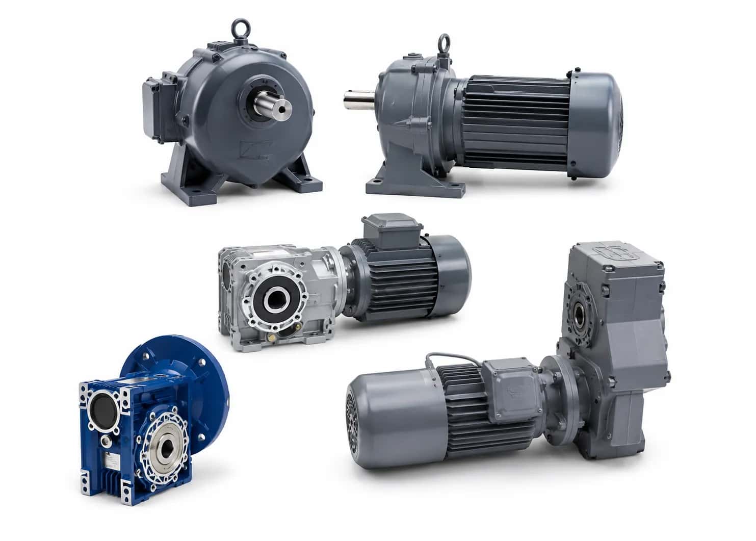
A geared motor consists of two main components:
Electric motor to generate rotational motion.
Gearbox to reduce speed and transmit torque to the output shaft.
Depending on the condition of the equipment, one of three options can be chosen:
Option | Items to check |
|---|---|
Replace the entire geared motor | Voltage, power, speed, torque, gear ratio, mounting type, and dimensions |
Replace only the electric motor | Power, speed, voltage, flange, input shaft, and connection type to the gearbox |
Replace only the gearbox | Gear ratio, torque, motor input, output shaft, shaft orientation, and mounting dimensions |
Do not assume that a motor with the same power can be mounted directly onto an old gearbox. Flanges, input shafts, drive gears, or adapter sets may vary between designs.
1. Model and nameplate information
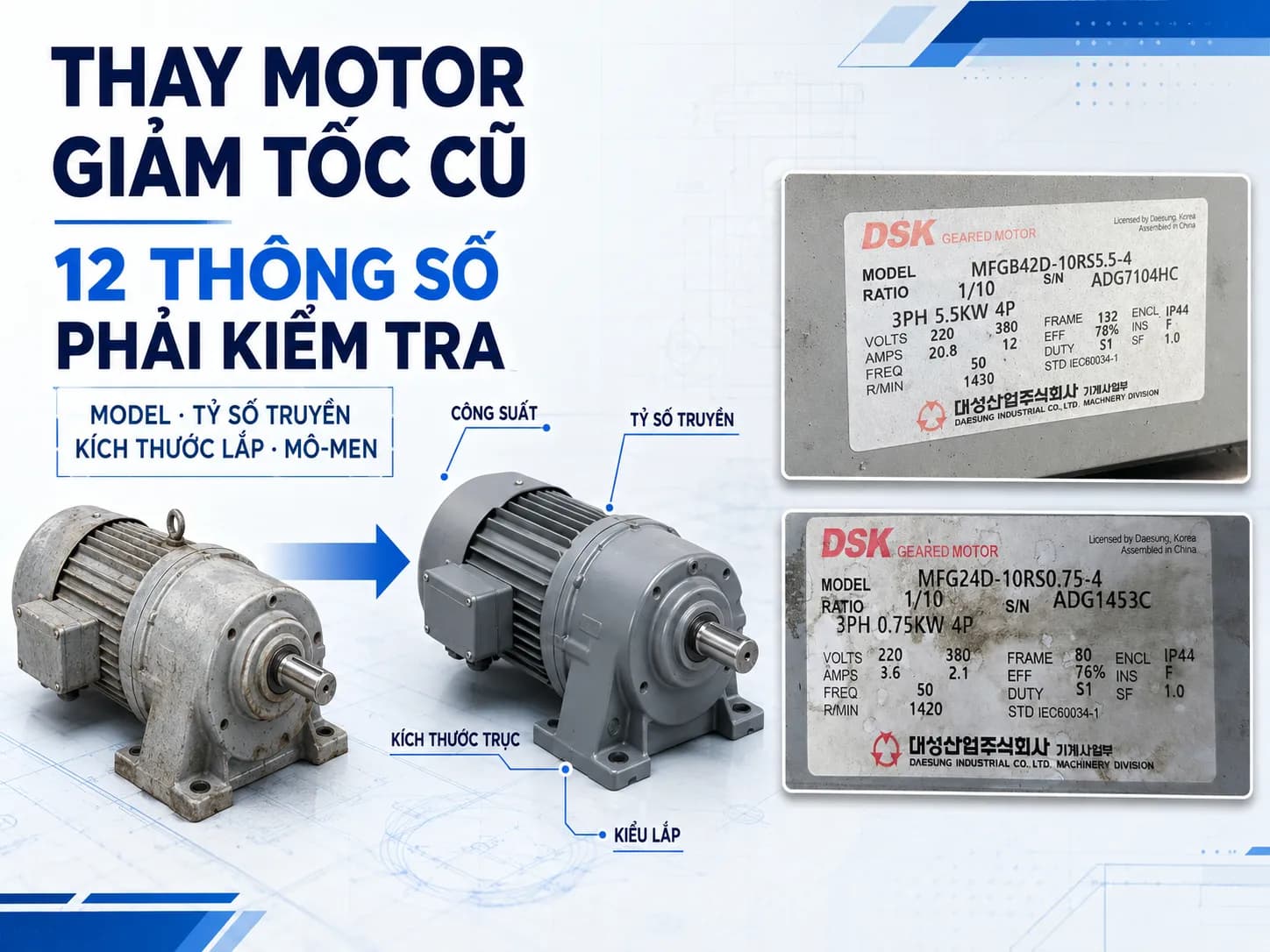
The first step is to record all legible information on the motor and gearbox nameplates:
Model
Power
Voltage
Frequency
Current
Motor speed
Gear ratio
Output speed
Mounting type
Brake voltage (if applicable)
Protection class
Duty cycle

DSK geared motor nameplate model MFG24D-10RS0.75-4, power 0.75 kW, 4 poles, gear ratio 1/10, voltage 220/380 V, and frame 80.
It is recommended to take separate photos of the motor nameplate, the gearbox label, and an overall view of the drive assembly. The overall view helps in identifying the motor position, shaft orientation, mounting type (foot or flange), and available installation space.
The old model is important data but not the sole basis for selection. If the load, capacity, or operating time has changed, it is necessary to recalculate rather than simply copying the previous configuration.
2. Application and load characteristics
It is necessary to identify what equipment the geared motor is being used for:
Conveyor
Screw conveyor
Agitator
Feeder
Winch drum
Packaging machine
Lifting mechanism
Reversible system
Then, evaluate the load characteristics:
Constant or variable load
Presence of shock loads
No-load or full-load start
Risk of mechanical jamming
Frequent reversing
Operating hours per day
Number of starts per hour
If the old equipment failed due to overload, replacing it with the exact same model may lead to recurring failures. It is necessary to check if the machine load has increased, if the material has changed, or if the operating cycle is more demanding than the original design.
3. Motor power
Motor power is usually expressed in kW or HP. When replacing, it is necessary to check:
Rated power
Full-load current
Starting current
Overload condition
Actual mechanical power required by the machine
Do not automatically increase the power just because the old motor was running weakly. A larger motor may transmit torque exceeding the load capacity of the gearbox, shaft, gears, chains, or couplings.
Before increasing the power, check for other causes:
Low supply voltage
Brake not fully released
VFD current limit
Acceleration time too short
Jammed load
Seized bearings or gearbox
Inappropriate gear ratio
Correct power does not necessarily mean the drive system is correctly selected.
4. Motor speed, number of poles, and frequency
Two motors with the same power but different numbers of poles will have different rated speeds. This directly changes the output speed and torque of the geared motor assembly.
It is necessary to cross-reference:
Rated speed on the nameplate
Number of motor poles
50 Hz or 60 Hz frequency
Direct-on-line motor or VFD-driven
Actual operating frequency
Do not use synchronous speed as a substitute for rated speed. Asynchronous motors have slip, so the actual speed is usually lower than the synchronous speed and varies with the load.
If the old motor was driven by a VFD, it is necessary to determine the actual operating speed of the machine instead of just reading the rated speed on the label.
5. Gear ratio and output speed
The fundamental relationship between motor speed and output speed is:
n₂ = n₁ / i
Where:
n₁: motor speed, rpm
n₂: output speed, rpm
i: gear ratio
For example, a motor with a speed of 1,400 rpm combined with a gear ratio of 35:
n₂ = 1,400 / 35 = 40 rpm
This is only the theoretical speed. The actual speed depends on the motor's rated speed and load conditions.
When replacing an old gear motor, prioritize the output speed that the machine actually requires. Even with the same gear ratio, if the new motor has a different speed, the output shaft speed will also change.
If the gear ratio cannot be read, you can:
Measure the output speed while the machine is still operating
Check machine documentation or drawings
Determine it from the production line capacity
Rotate the input shaft and count the output revolutions after the device has been safely disassembled
6. Output Torque and Service Factor
For the same power, the lower the output speed, the higher the torque.
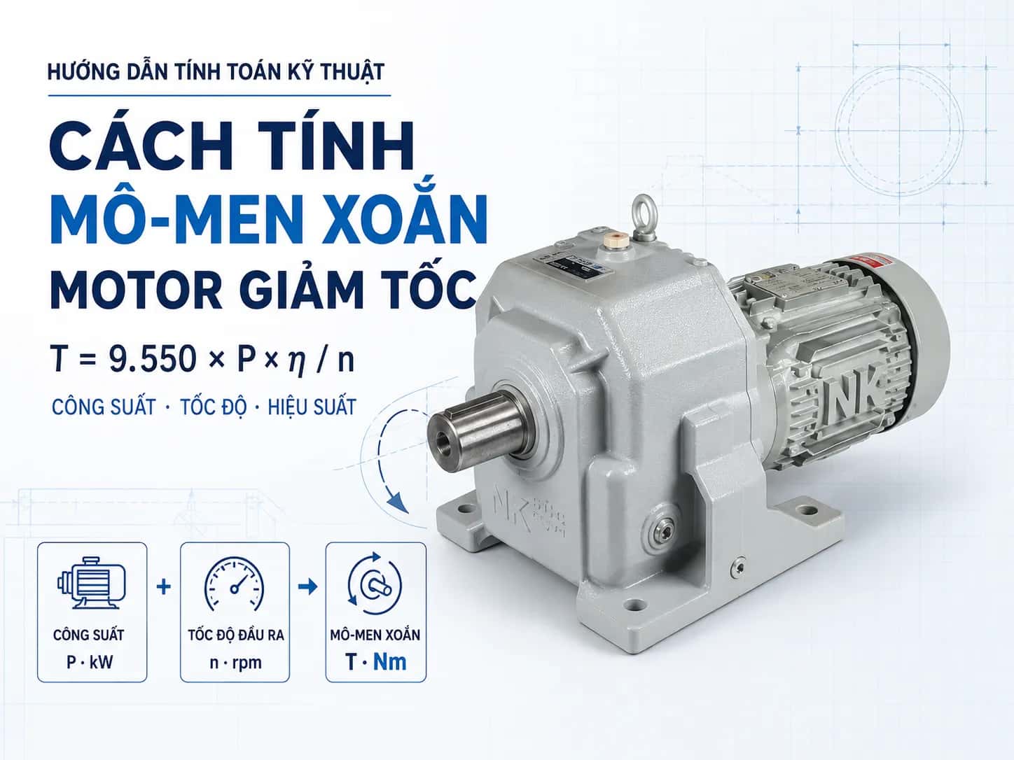
When the mechanical power at the specific shaft in question is known, torque can be estimated using the formula:
T = 9,550 × P / n
Where:
T: torque, Nm
P: mechanical power, kW
n: speed, rpm
If using the motor power to estimate torque at the gearbox output, transmission efficiency must be taken into account.
In addition to operating torque, check for:
Starting torque
Peak torque
Shock loads
Number of starts
Number of reversals
Operating time
Required Service Factor
A gearbox may have sufficient torque during steady-state operation but can still be overloaded during starting, reversing, or load jamming.
Do not apply a fixed Service Factor value to all applications. Selection must be based on load characteristics, duty cycle, and the load-bearing capacity of the specific model.
7. Gearbox Type and Output Shaft Orientation
It is necessary to determine the configuration of the old gearbox:
Coaxial
Parallel shaft
Right-angle drive
Solid shaft
Hollow shaft
Single output shaft
Double output shaft
For right-angle or parallel shaft gearboxes, the output shaft orientation is particularly important. A new device may have the correct power and gear ratio but still cannot be installed if the shaft is on the wrong side or the motor faces the machine frame.
When submitting a replacement request, it is recommended to photograph the device from:
The motor side
The output shaft side
The top
Both sides of the device
The entire mounting position on the machine
8. Mounting Style and Installation Position
Common configurations include:
Foot mounting
Flange mounting
Shaft mounting
Horizontal mounting
Vertical mounting
Motor positioned above, below, or to the side of the gearbox
The mounting position not only relates to mechanical space but also affects:
Oil level
Breather plug position
Oil drain position
Lubrication capability
Oil seals
Bearings
Do not attempt to convert a gear motor from horizontal to vertical mounting without verifying the lubrication configuration of the new model.
For replacement equipment, the operating position must be clearly defined at the time of model selection and ordering.
9. Output shaft dimensions and keyway
Shaft dimensions determine the compatibility with existing sprockets, pulleys, couplings, or machine shafts.
For solid shafts
Required measurements:
Shaft diameter
Length of the protruding shaft section
Keyway dimensions
Key length
Distance from the shaft shoulder to the shaft end
Threads or center holes if applicable
For hollow shafts
Required checks:
Bore diameter
Mounting length
Keyway dimensions
Machine shaft diameter
Torque arm
Clearance for installation and removal
Two shafts with the same diameter but different lengths or keyways may still be incompatible with existing transmission components.
Avoid force-fitting or arbitrary shaft machining without verifying structural integrity and torque transmission capability.
10. Foot, flange dimensions, and center height
These parameters determine whether the new gear motor will fit the existing mounting location.
For foot-mounted types
Required measurements:
Longitudinal bolt hole spacing
Transverse bolt hole spacing
Hole diameter
Foot length and width
Height from the base to the shaft center
Distance from the gearbox center to the shaft end
For flange-mounted types
Required measurements:
Flange outer diameter
Pilot diameter
Bolt circle diameter
Number of bolt holes
Hole diameter
Shaft length
Distance from the flange face to the shaft end
Similar external appearance does not imply equivalent dimensions. Always cross-reference drawings before finalizing replacement equipment.
If machine base modification is required, ensure proper center height, alignment, and structural rigidity.
11. Voltage, frequency, and connection type
Simultaneous verification is required for:
Rated voltage
Frequency
Number of phases
Rated current
Star or delta connection type
Rated speed
Actual power supply at the facility
Do not consider voltage independently of frequency. Motors with the same voltage but designed for different frequencies may result in different speeds and operating conditions.
If using a VFD, additional checks are required:
Input and output voltage
Motor rated current
Base frequency
Operating frequency range
Control mode
Acceleration and deceleration time
After replacing the motor, the parameters in the VFD must also be updated according to the new equipment's nameplate.
12. Brakes, encoders, and operating conditions
If the old geared motor has accessories, it is necessary to accurately identify:
Electromagnetic brake
Brake coil voltage
Brake rectifier
Encoder
Forced cooling fan
Backstop
Thermal switch
Speed sensor
Additionally, it is necessary to check the operating conditions:
Daily operating hours
Number of starts per hour
Reversible operation
Ambient temperature
Dust, moisture, or water
Indoor or outdoor installation
Direct-on-line or VFD-driven operation
Requirement for load holding during power failure
If the old motor has a brake, the correct brake voltage and switching method must be determined. If the motor operates at low speeds for extended periods, torque and cooling capacity must be verified.
Procedure for replacing old geared motors
Step 1: Capture complete equipment information
It is necessary to clearly photograph:
Motor nameplate
Gearbox label
General view
Output shaft
Foot mount or flange
Sprocket, pulley, or coupling
Mounting position on the machine
The general view photo should show the motor orientation, shaft direction, and installation clearance. Sending only the nameplate photo is often insufficient to verify replacement compatibility.
Step 2: Determine the reason for replacement
Geared motors may be replaced due to:
Motor burnout
Gear damage
Bearing wear
Oil leakage
Insufficient torque
Obsolete spare parts
Productivity increase
Machine retrofitting
If the cause is overload, misalignment, mechanical jamming, or weak machine structure, it must be addressed before installing the new equipment.
Step 3: Measure actual dimensions
Do not estimate dimensions from images. It is necessary to measure directly:
Shaft diameter and length
Keyway dimensions
Foot hole spacing
Center height
Flange dimensions
Pilot diameter
Installation space
Clearance for disassembly and maintenance
If machine drawings or old equipment drawings are available, they should be used in conjunction with actual measurements.
Step 4: Verify parameters before selecting a new model
Before finalizing the replacement geared motor, it is necessary to confirm:
Power rating
Voltage and frequency
Motor speed
Gear ratio
Output speed
Operating torque
Starting torque
Gearbox type
Output shaft orientation
Mounting type
Shaft dimensions
Brake and accessories
The new equipment does not necessarily have to be identical in appearance, but parameters affecting operation and installation must be compatible.
Step 5: Post-installation inspection
After installing the new gear motor, it is necessary to check:
Direction of rotation
Concentricity
No-load and load current
Output speed
Vibration
Noise
Temperature
Brake operation
Oil level
Leakage status
If a VFD is used, it is necessary to enter the correct motor parameters and set appropriate acceleration and deceleration times before running under load.
Frequently Asked Questions
Can I replace a gear motor with a different model but the same power rating?
It may be considered, but you must also compare the speed, torque, gear ratio, shaft orientation, mounting type, dimensions, and electrical parameters.
If the gear ratios are the same, will the output speeds be the same?
Not necessarily. The output speed also depends on the rated speed of the motor and the operating frequency.
Should I choose a new motor larger than the old one?
Only increase the power after recalculating the load and checking the torque capacity of the gearbox and the entire transmission mechanism.
What should I do if the nameplate is unreadable?
You need to measure the dimensions, identify the application, load, output speed, and power supply. You can refer to machine drawings or measure the speed while the system is still operational.
If the new motor does not fit the base, can the machine base be modified?
It is possible in some cases, but you must check the center height, concentricity, maintenance space, and the rigidity of the base.
Is it necessary to replace the gears or couplings?
They must be replaced or re-machined if the shaft diameter, shaft length, or keyway of the new equipment is incompatible.
MDriveTech supports old gear motor replacement
MDriveTech provides support for inspecting and selecting gear motors, DSK, Nara Samyang, and NK gearboxes for replacement or machine retrofitting needs.
Customers should send photos of the nameplate, installation position, shaft dimensions, output speed, application, and load conditions for configuration matching before placing an order.
Hotline: 0868 789 647
Email: [email protected]
Conclusion
When replacing an old gear motor, do not choose solely based on power or gear ratio. The replacement equipment must simultaneously meet the requirements for speed, torque, Service Factor, gearbox type, mounting position, shaft orientation, mechanical dimensions, and electrical parameters.
Measuring actual dimensions and checking drawings before ordering helps prevent issues such as the new equipment not fitting, running at the wrong speed, or lacking torque. If the old gear motor failed due to overload or improper installation, the root cause must be addressed before putting the new unit into operation.