How to Accurately Calculate Output Torque for Geared Motors
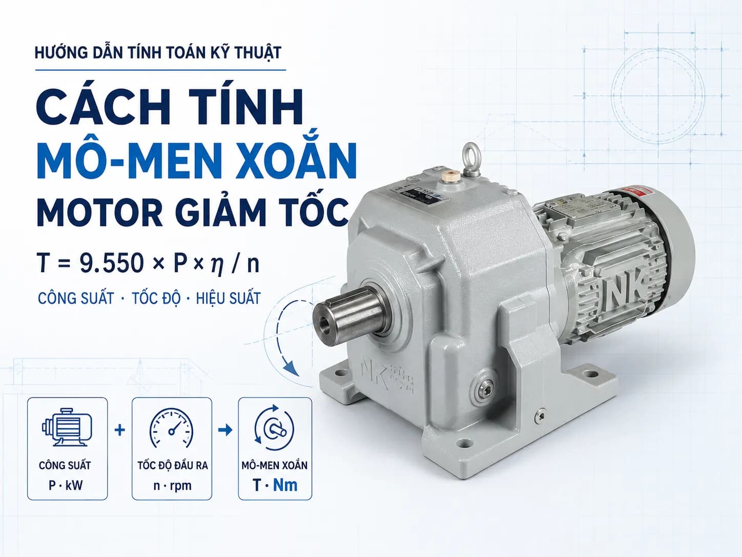
A comprehensive guide on calculating geared motor torque based on power, speed, gear ratio, and actual load, including formulas, practical examples, and selection tips.
How to Accurately Calculate Output Torque of a Geared Motor
Output torque indicates the ability of a geared motor to pull, rotate, lift, or hold a load. Two drive systems with the same power but different output speeds will generate completely different torque.
To calculate geared motor torque, it is necessary to know the motor power, output speed, gear ratio, and transmission efficiency. After calculation, it must be cross-referenced with the rated torque in the catalog, the service factor, and actual operating conditions before selecting a model.
What is geared motor torque?
Torque is the ability to generate rotational force around an axis. The unit commonly used in industrial drive systems is Newton-meter – Nm.
Torque depends on the applied force and the distance from the point of force application to the axis center:
T = F × r
Where:
T: torque, in Nm.
F: applied force, in N.
r: radius of force application, in m.
For example, a force of 500 N applied to a drum with a radius of 0.2 m will generate a torque of:
T = 500 × 0.2 = 100 Nm
The larger the drum radius or lever arm, the higher the required torque, even if the load force remains unchanged.
Distinguishing between motor torque and gearbox output torque
Electric motors rotate fast but generate relatively low torque. A gearbox reduces speed and increases torque at the output shaft.
Distinctions can be made as follows:
Input torque: torque at the motor shaft.
Output torque: torque after the gearbox.
Load torque: actual torque required by the machine.
Rated torque: the value at which the gearbox can operate continuously according to the manufacturer's specifications.
Peak torque: a higher load level only permitted under limited conditions and durations.
When selecting, the rated output torque of the geared motor must meet the load torque after accounting for starting conditions and the service factor.
Formula for calculating torque from power and speed
The common formula for calculating the torque of a rotating shaft is:
T = 9,550 × P / n
Where:
T: torque, in Nm.
P: power at the shaft being calculated, in kW.
n: shaft speed, in rpm.
9,550: conversion factor between power, rotational speed, and torque.
If using input motor power to estimate torque after the gearbox, efficiency must be considered:
T₂ = 9,550 × P₁ × η / n₂
Where:
T₂: gearbox output torque, Nm.
P₁: motor power, kW.
η: total efficiency of the gearbox and transmission system.
n₂: output speed, rpm.
One should not estimate efficiency without knowing the gearbox type, gear ratio, and number of gear stages. The appropriate value should be verified in the manufacturer's technical documentation.
Example of calculating output torque for a geared motor
Assume the system uses:
Motor power: 1.5 kW.
Output speed: 50 rpm.
Assumed efficiency for preliminary calculation: 0.9.
Estimated output torque:
T₂ = 9,550 × 1.5 × 0.9 / 50
T₂ ≈ 258 Nm
If losses are ignored, the theoretical result would be:
T = 9,550 × 1.5 / 50 ≈ 286.5 Nm
The difference between 286.5 Nm and 258 Nm represents the assumed power loss within the gearbox. When selecting a product, it is recommended to prioritize the output torque value published in the catalog rather than relying solely on theoretical results.
Calculating torque based on motor torque and gear ratio
Once the motor input torque is known, the output torque can be calculated preliminarily using the formula:
T₂ = T₁ × i × η
Where:
T₁: motor input torque, Nm.
T₂: gearbox output torque, Nm.
i: gear ratio.
η: total efficiency.
Example:
Motor torque: 10 Nm.
Gear ratio: 30.
Assumed efficiency: 0.9.
Result:
T₂ = 10 × 30 × 0.9 = 270 Nm
The higher the gear ratio, the higher the theoretical output torque, but the output speed will decrease. Additionally, the dimensions and load-bearing limits of the gearbox must still be verified.
[Internal link suggestion: article “How to calculate gearbox gear ratio”.]
Relationship between power, speed, and torque
These three quantities are directly related:
Keeping power constant, if speed decreases, torque increases.
Keeping speed constant, if power increases, torque increases.
To increase output speed under the same power conditions, the available torque will decrease.
Example with the same 1.5 kW mechanical power and excluding losses:
Output speed | Theoretical torque |
|---|---|
100 rpm | Approx. 143 Nm |
50 rpm | Approx. 287 Nm |
25 rpm | Approx. 573 Nm |
The table above only illustrates the mathematical relationship. It cannot be concluded that a 1.5 kW motor can always provide these torque levels, as it also depends on the mechanical limits of the gearbox and operating conditions.
How to calculate load torque from force and radius
In many applications, it is necessary to calculate the load torque first before selecting a geared motor.
Basic formula:
T load = F × r
Example for a conveyor pulley with:
Required pulling force: 800 N.
Pulley radius: 0.15 m.
Torque at the pulley:
T load = 800 × 0.15 = 120 Nm
This is only the basic load torque. When making an actual selection, the following must also be considered:
Conveyor friction.
Inclination angle.
Starting load.
Losses in the chain drive or coupling.
Operating hours.
Number of starts.
Potential for load jamming.
Service factor of the gearbox.
It is not recommended to take 120 Nm and select a motor with exactly 120 Nm of torque without checking the above factors.
Calculating torque for conveyors
For conveyors, the preliminary calculation procedure includes:
Determine the total required pulling force.
Determine the drive pulley radius.
Calculate the torque at the pulley.
Account for the efficiency of the transmission mechanism.
Account for starting torque and service factor.
Select an appropriate output speed.
Cross-reference with catalog torque.
Preliminary formula:
T pulley = F pulling × r pulley
If the geared motor drives through a chain sprocket, it is necessary to calculate the gear ratio and the efficiency of the chain drive.
[Internal link suggestion: “Geared Motor” category and the article “How to select a geared motor based on load, speed, and operating time”.]
Calculating torque for lifting mechanisms
For simple lifting mechanisms using a cable drum, the static load torque can be estimated as:
T = m × g × r
Where:
m: lifting mass, kg.
g: gravitational acceleration, approximately 9.81 m/s².
r: drum radius, m.
Example for lifting a 100 kg load with a 0.1 m radius drum:
T = 100 × 9.81 × 0.1 = 98.1 Nm
This result does not include acceleration, losses, dynamic loads, cable mechanisms, braking systems, and safety requirements. Lifting equipment must be calculated according to appropriate standards and safety designs; it should not be selected based solely on the static load formula.
Calculating torque for screw conveyors and agitators
For screw conveyors or agitators, torque is difficult to determine solely from the material mass. It also depends on:
Material characteristics.
Density.
Moisture and cohesiveness.
Screw diameter and length.
Fill level.
Inclination angle.
Viscosity of the agitated substance.
Agitator blade shape.
Required speed.
Starting conditions.
If the machine is already in operation, data on current, power of the old motor, and load status are useful reference bases. For new machines, it is recommended to use specific calculation methods for each type of equipment or data from the machine manufacturer.
Is starting torque important?
Yes. The torque when the machine starts running can be significantly higher than the torque in a steady state.
Special attention is required when:
The conveyor starts under full load.
The screw conveyor contains material.
The mixer contains viscous material.
The hoist begins to lift a load.
The mechanism reverses continuously.
The machine has high inertia.
The system uses direct-on-line starting.
A VFD helps adjust acceleration time and limits mechanical shock, but the motor must still generate sufficient torque at the required speed range.
How does the load factor affect the selection?
Calculated torque based on formulas often does not fully reflect actual operating conditions. Therefore, it is necessary to consider the load factor or service factor.
The load factor depends on:
Steady or shock loading.
Daily operating hours.
Number of starts.
Frequency of reversals.
Ambient temperature.
Continuous or intermittent duty cycle.
Type of driven machine.
There is no universal factor suitable for all gearboxes. It is essential to use the selection tables from the specific manufacturer and series.
Do not confuse torque with radial load
A gearbox with sufficient torque may not be suitable if the output shaft is subjected to excessive radial load.
Radial loads typically occur when the shaft end is equipped with:
Sprockets.
Belt pulleys.
Gears.
Drive drums.
The further the sprocket or pulley is mounted from the shaft shoulder, the greater the load on the shaft and bearings. Therefore, it is necessary to check torque, radial load, and the force application point simultaneously.
Axial load must also be checked if the mechanism generates pulling or pushing forces along the shaft axis.
Common mistakes when calculating geared motor torque
Using motor speed instead of output speed.
Neglecting gearbox efficiency.
Confusing radius with drum diameter.
Confusing units of mm with m.
Using mass in kg directly as force in N.
Not calculating starting torque.
Not considering shock loads and operating hours.
Relying solely on theoretical torque without checking the catalog.
Not checking radial and axial loads.
Applying a fixed safety margin for all applications.
For example, a drum with a diameter of 300 mm has a radius of 150 mm, which is equivalent to 0.15 m. If 300 is used instead of 0.15 in the formula, the result will be significantly incorrect.
However, the calculation result is only a preliminary selection step. The actual model must meet the rated torque, starting torque, load factor, radial load, axial load, and operating time requirements.
MDriveTech provides support for torque calculation and geared motor selection based on load, speed, gear ratio, and machine structure. Customers can provide load parameters, drum diameter, required speed, drawings, or photos of the equipment nameplate to have the appropriate model checked and recommended.
📞 Hotline: 0868 789 647
📧 Email: [email protected]
Frequently Asked Questions
Is a higher torque always better for a gear motor?
No. The torque must be matched to the load and speed of the machine. Selecting an excessively high torque increases costs, dimensions, and installation requirements. The most important factor is having sufficient safety margin based on actual operating conditions.
Why do motors with the same power rating have different torque values?
Because torque is dependent on speed. For the same power, a slower rotating shaft will generate higher torque. This is why gearboxes reduce speed to increase output torque.
Can torque be calculated without considering efficiency?
It is possible to calculate theoretical torque, but the result will be higher than the actual torque. When selecting equipment, it is recommended to use the efficiency provided by the manufacturer or refer directly to the output torque in the catalog.
Should torque be calculated using the diameter or radius of the drum?
The radius must be used. If only the diameter is available, it must be divided by two and converted to meters before being applied to the formula T = F × r.
Is the calculated torque equal to the catalog torque sufficient?
Not necessarily. It is necessary to consider starting torque, service factor, operating time, shock loads, and forces acting on the shaft. The catalog torque should be higher than the required level after applying appropriate selection criteria.