Gear Motors for Feeding Systems: How to Select Speed, Torque, and Power
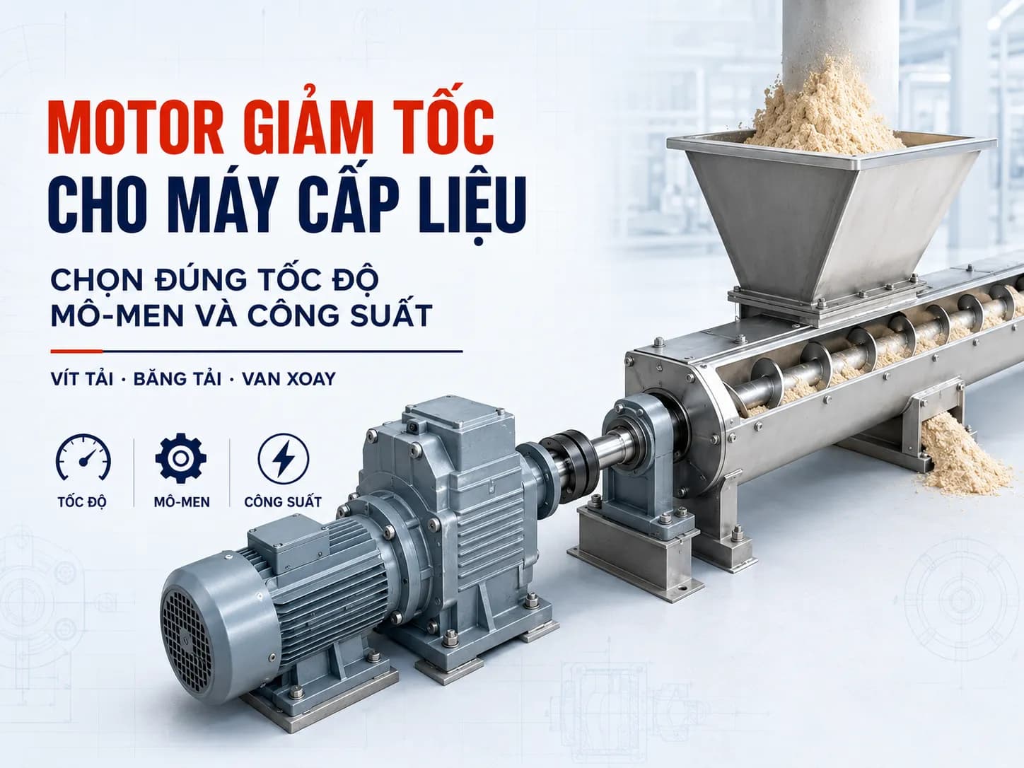
A guide to selecting gear motors for feeding systems based on speed, torque, power, and material properties. Suitable for screw conveyors, belt conveyors, rotary valves, and chain conveyors.
Geared Motors for Feeders: How to Select Speed, Torque, and Power
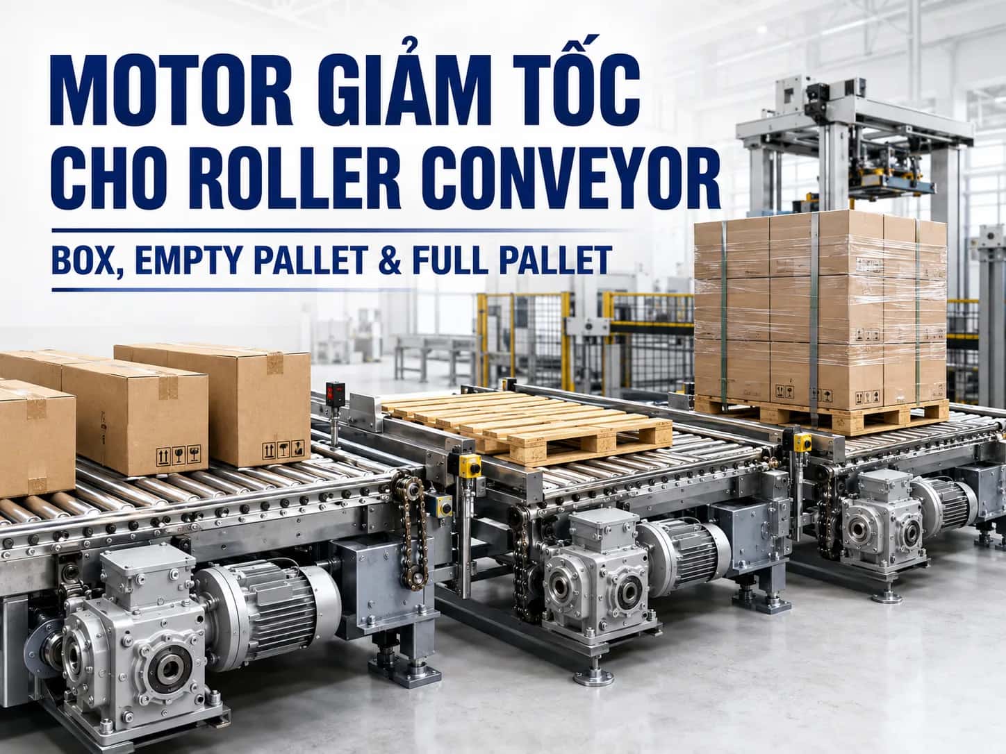
Geared motors for feeders are drive assemblies consisting of an electric motor and a gearbox, designed to provide low output speed and the appropriate torque for conveying or metering materials. This configuration is commonly used for screw feeders, belt conveyors, chain conveyors, rotary valves, and screw metering machines.
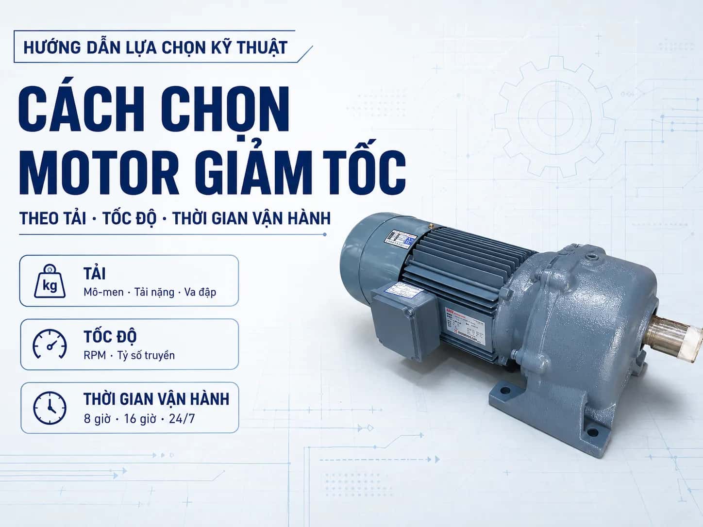
Selection cannot be based solely on motor power. A drive with sufficient kW may still fail to start when the machine is full of material, operate at the wrong flow rate, or suffer premature failure if the gear ratio, torque, mounting style, and external loads are not suitable. Therefore, it is necessary to consider throughput, output speed, material characteristics, starting load, and operating mode simultaneously.
Do feeders use geared motors or gearboxes?
In most rotary feeders, the equipment used is a complete geared motor. The motor generates motion, while the gearbox reduces the speed and helps achieve the required output torque at the machine shaft.
Feeder gearbox is the appropriate term when the gearbox is installed separately and receives input from:
A separately mounted electric motor
Couplings
Belt or chain drives
Intermediate shafts
An existing drive source on the machine
The distinction can be made as follows:
Configuration | Characteristics | Suitable Application |
|---|---|---|
Integral geared motor | Motor and gearbox form a single unit | Small to medium-capacity feeders requiring compact installation |
Separately mounted motor and gearbox | Two independent devices connected by a coupling or intermediate drive | Heavy loads, requiring separate motor placement or ease of maintenance |
Gearbox without motor | Performs only the speed reduction function | Systems with an existing drive source |
For those looking to purchase a complete drive assembly, geared motor for feeders is the term that more closely aligns with practical applications. However, the final configuration must still be based on the machine structure and installation requirements.
Common types of feeders using gear motors
Screw feeders
Screw feeders use a screw flight to transport powder, granules, or bulk materials horizontally or at an incline.
Characteristics of screw feeder loads:
Low output speed is typical
Relatively high operating torque
Starting with material is more difficult than starting empty
Moist, sticky, or caked materials can cause significant load spikes
Screw shafts may generate axial loads
Long screws require support from appropriate bearings
Gear motors for screw conveyors must be verified against actual starting conditions. The gearbox shaft should not be subjected to the full weight, bending moment, and axial force of the screw assembly without proper calculation.
Belt feeders
Belt feeders deliver material to crushers, mixers, packaging machines, or subsequent production stages.
Drive requirements typically include:
Stable belt speed
Ability to start under load
Adjustable flow rate
Smooth operation, minimizing load jerks
Check radial loads at sprockets, pulleys, or drive drums
If the transmission from the gearbox to the drum is via chain or belt, pay attention to sprocket diameter, tension, and mounting position relative to the shaft shoulder. For inclined conveyors, the risk of load rollback during machine stops must be evaluated.
Chain feeders
Chain feeders are suitable for heavy materials, high loads, or operating conditions involving impact.
Common characteristics:
Relatively low speed
High output torque
Heavy starting load
Load varies with material volume
Impacts may occur at the chain and pulling mechanism
Chain feeder motors should not be selected based solely on average power. It is necessary to check starting torque, peak torque, number of starts, and the load-bearing capacity of the gearbox.
Rotary valves
Rotary valves use rotating vanes to move powder or granules through individual metering chambers.
Although the motor power may not be high, the drive unit must still meet the following:
Low and stable rotational speed
Sufficient torque to overcome friction
Ability to start when loaded with material
Risk of particles jamming between vanes and housing
Ability to adjust flow rate via speed control
Protection schemes for overload/jamming
Rotary valve motors should be selected based on actual torque, not just the motor size used on a similar machine.
Screw metering feeders
Screw metering feeders require stable rotational speed because screw speed directly affects material flow rate.
When selecting, check the following:
Screw diameter and pitch
Screw fill level
Material flow characteristics
Speed adjustment range
Flow rate stability
Starting and stopping loads
Vibratory feeders are a different case. This type typically uses vibration motors, electromagnetic vibrators, or specialized oscillation mechanisms, and does not default to using geared motors.
How to select a geared motor for a feeder
Determine the material to be fed
Material characteristics directly affect load torque and starting capability.
Important information includes:
Bulk density
Particle size
Moisture content
Stickiness
Caking tendency
Abrasiveness
Material temperature
Flowability
For the same machine, switching from dry granules to moist or sticky material can significantly increase the load. Therefore, do not maintain the same geared motor configuration when material characteristics have changed.
Determine the feeding capacity
Capacity can be expressed in:
kg/h
t/h
m³/h
L/min
products/min
It is not possible to convert capacity directly into motor power without knowing the machine's principle and dimensions.
For screw conveyors, it is necessary to include screw diameter, pitch, length, inclination angle, and fill ratio. For belt conveyors, it is necessary to know the belt length, width, inclination angle, material load, and pulley diameter.
Determine the output speed
Output speed directly affects the feeding flow rate.
The basic relationship between motor speed and gear ratio is:
n₂ = n₁ / i
Where:
n₁: motor speed, rpm
n₂: output speed, rpm
i: gear ratio
For example, a motor with a speed of 1,400 rpm combined with a gear ratio of 28:
n₂ = 1,400 / 28 = 50 rpm
This is only the theoretical speed. The actual speed also depends on motor characteristics, load, and slip. The example above is not a recommendation to use 50 rpm for all feeders.
Calculate operating torque
Once the mechanical power at the specific shaft is known, torque can be approximately calculated as:
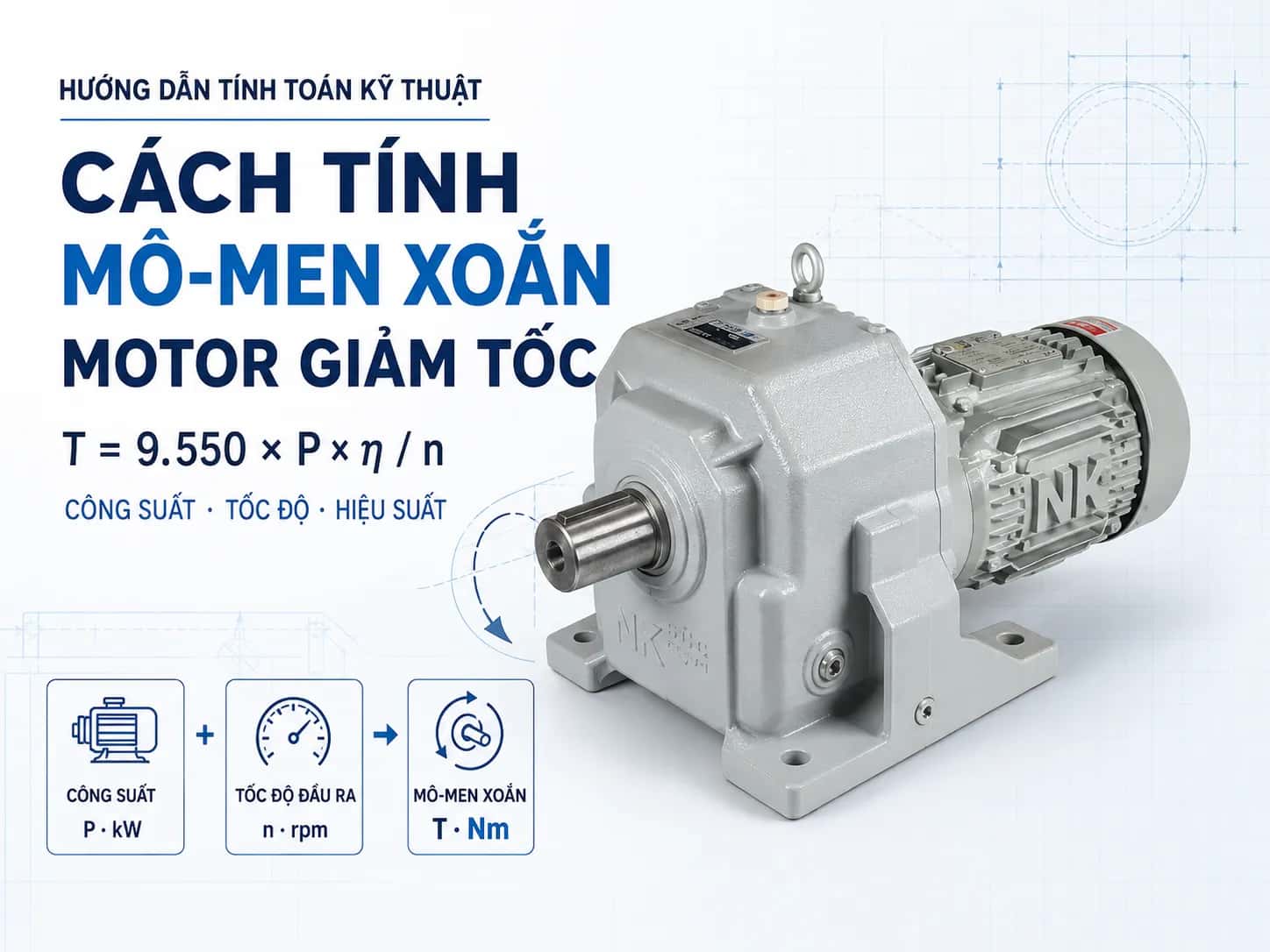
T = 9,550 × P / n
Where:
T: torque, Nm
P: mechanical power, kW
n: speed, rpm
If using motor power to estimate torque at the gearbox output, transmission losses must be taken into account. Do not simply multiply motor power by the gear ratio and consider that the actual output torque.
Initial calculation results are only for preliminary selection. The final model must meet the continuous torque, short-term load, and operating conditions of the machine.
Check starting torque
Feeders often require higher starting torque when:
The screw is full of material
The conveyor starts under full load
Material is compressed or caked
The rotary valve is jammed with particles
The machine has been stopped for a long time with material inside
The mechanism has high static friction
The motor must generate sufficient torque to overcome initial resistance and accelerate the system. The gearbox must also withstand short-term torque during the startup process.
A drive system may have sufficient torque for steady-state operation but may still fail to start if the starting torque is inadequate.
Operating mode check
It is necessary to clearly determine:
Continuous or batch operation
Daily operating hours
Number of starts per hour
Reversing or non-reversing
No-load or full-load startup
Load variation level
Ambient temperature
Dust and humidity levels
Machines operating continuously, starting frequently, or prone to jamming require different evaluation compared to those operating intermittently with stable loads.
Radial and axial load check
Sprockets, pulleys, gears, and drive drums exert radial loads on the gearbox shaft. These loads increase when:
Sprockets or pulleys have small diameters
Chains or belts are over-tensioned
Drive components are mounted far from the shaft shoulder
The load involves impact
Drums or pulleys have significant weight
Screw conveyors can also generate axial loads due to the material thrust force. Long screw shafts or drums require separate support bearings. The gearbox shaft should not be used as the sole support unless its load-bearing capacity has been verified.
Selecting the appropriate geared motor type
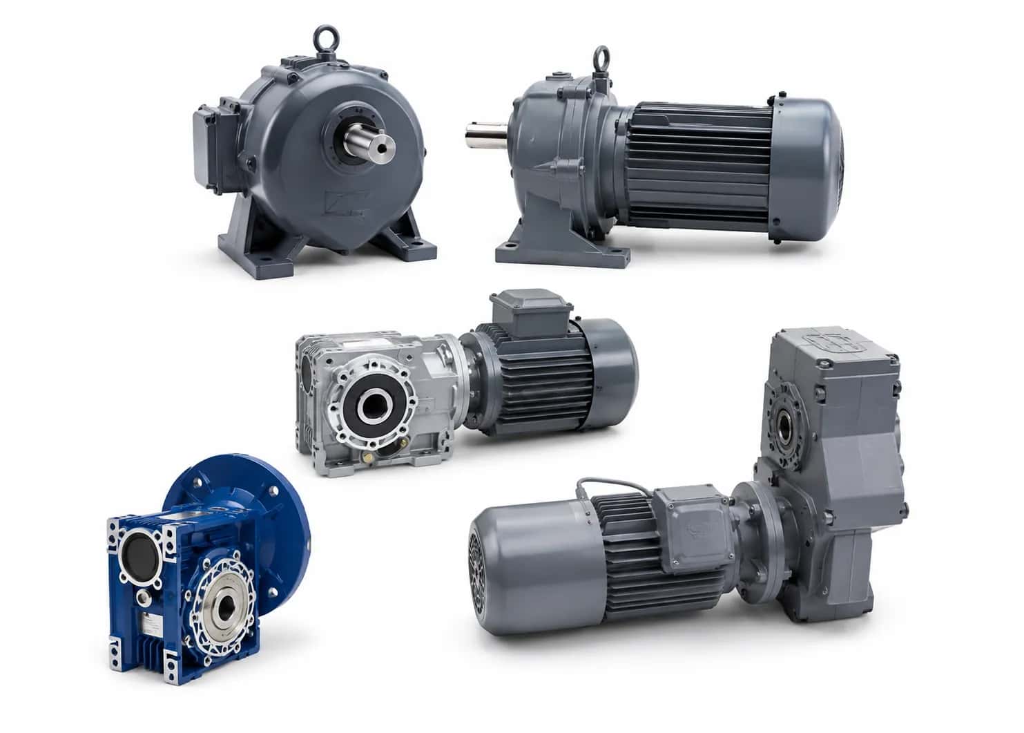
Helical geared motor
Suitable for conveyors, screw feeders, rotary valves, and metering machines where relatively quiet operation, high transmission efficiency, and continuous duty are required.
Foot-mounted or flange-mounted versions can be selected depending on the machine structure.
Parallel shaft geared motor
Suitable when high output torque is required and the motor needs to be arranged parallel to the machine shaft. This configuration often helps reduce the overall axial length.
Right-angle geared motor
Suitable when a 90-degree change in transmission direction is required or when space for inline motor mounting is limited.
Suitability must be verified based on load, mounting position, and the specific gearbox type.
Hollow shaft geared motor
The hollow shaft design allows for direct mounting onto the machine shaft, reducing the need for couplings and resulting in a more compact drive arrangement.
Before selection, it is necessary to check:
Machine shaft diameter
Keyway
Mounting length
Torque arm
Clearance for installation and removal
Maintenance plan
There is no single geared motor type suitable for all feeding machines. Selection depends on space, load, transmission direction, and mechanical structure.
Should a VFD be used for feeding machines?
A VFD is suitable when there is a need for:
Adjusting feed rate
Soft starting and stopping
Synchronization with downstream processes
Multi-speed operation
Sensor-based control
Limiting starting current
However, reducing the motor speed too low for extended periods can impair its self-cooling capability. For loads requiring high torque at low speeds, the motor characteristics, control mode, and VFD overload capacity must be verified.
The parameters that must be set correctly include:
Motor voltage and current
Rated power and frequency
Acceleration time
Deceleration time
Current limit
Control mode
The VFD cannot resolve torque deficiency if the motor, gearbox, or gear ratio has been incorrectly selected.
Quick selection table by feeder type
Machine type | Load characteristics | Main drive requirements |
|---|---|---|
Screw feeder | Low speed, high torque, risk of jamming | Check starting torque and axial load |
Belt feeder | Relatively stable load | Constant speed, adjustable via VFD |
Inclined conveyor | Load prone to rollback | Check torque, brake, or backstop |
Chain feeder | Heavy load, shock loading | Check peak torque and load factor |
Rotary valve | Low speed, prone to jamming | Starting torque and overload protection |
Screw metering feeder | Requires stable flow rate | Speed regulation and material characteristic control |
Common selection mistakes
Selecting based solely on kW power
The same power rating with different output speeds will result in different torque. Power alone is insufficient to determine the appropriate drive assembly.
Failure to check starting load
The machine may run well when empty but fail to start when the screw, conveyor, or rotary valve is fully loaded with material.
Changing material without updating configuration
Materials with higher bulk density, high moisture content, or those prone to caking can cause a sharp increase in load torque.
Excessive speed reduction using VFD
Motors running at low speeds for extended periods may overheat and fail to maintain sufficient torque if not properly selected.
Allowing the gearbox shaft to bear the entire external load
Screw shafts, drums, and pulleys require appropriate support structures. Do not assume the gearbox shaft can serve as the primary bearing support.
Ignoring the possibility of material jamming
Torque when material is jammed or caked can be significantly higher than under normal operating conditions.
Failure to check mounting orientation
Horizontal, vertical, or inclined mounting can affect lubrication, oil seals, ventilation, and bearing service life.
Information required for selecting gear motors
To ensure accurate selection, customers should provide:
Feeder type
Material type
Bulk density
Required capacity
Output speed
Dimensions of the screw, conveyor, or rotary valve
Empty or full-load start
Operating hours
Number of starts
Reversing requirements
Mounting style
Shaft dimensions
VFD usage
Machine photos or drawings
Frequently Asked Questions
Should feeders use a gear motor or a standalone gearbox?
Most rotary feeders use a complete gear motor. A standalone gearbox is suitable when the motor and gearbox need to be arranged independently or if the machine already has a drive source.
What is the recommended RPM for a feeder gear motor?
There is no universal speed. The speed depends on the machine type, mechanism size, material characteristics, and required capacity.
Should motor power be increased if the machine jams?
Increasing power immediately is not recommended. It is necessary to check the material, mechanical clearances, gear ratio, starting torque, and the load-bearing capacity of the gearbox.
Can a VFD be used to adjust flow rate?
Yes. Changing the speed can adjust the flow rate of screw conveyors, belt conveyors, or rotary valves. However, it is essential to check the torque and motor cooling capacity at low speeds.
Can a screw conveyor be connected directly to the gearbox shaft?
Direct connection is possible, but the screw shaft still requires an appropriate support system. The gearbox shaft should not bear the entire weight and axial load of the screw.
Do inclined feeders require a brake or backstop?
This may be necessary if the load tends to back-drive when stopped. The selection depends on the machine structure, load level, and safety requirements.
MDriveTech consulting for feeder gear motors
MDriveTech provides support for selecting DSK, Nara Samyang, and NK gear motors and gearboxes for:
Screw feeders
Belt feeders
Chain feeders
Rotary valves
Dosing machines
Material feeding systems
For proper selection, customers should provide information regarding material, capacity, output speed, mechanism dimensions, mounting style, and starting conditions.
Hotline: 0868 789 647
Email: [email protected]
Conclusion
Most screw feeders, conveyors, chain conveyors, or rotary valves utilize gearmotors to achieve low speeds and appropriate torque. Separate gearboxes are used when the motor and gearbox need to be arranged independently or when the system already has an existing drive source.
When selecting a gearmotor for a feeder, it is necessary to simultaneously evaluate speed, torque, material, capacity, starting load, and installation conditions. Do not rely solely on kW power ratings or copy configurations from a machine operating under different conditions.