How to Select a Geared Motor Based on Load, Speed, and Operating Time
A guide on how to select a geared motor based on load, torque, speed, gear ratio, and operating time, helping to prevent overload and incorrect power selection.
How to Select a Geared Motor Based on Load, Speed, and Operating Time
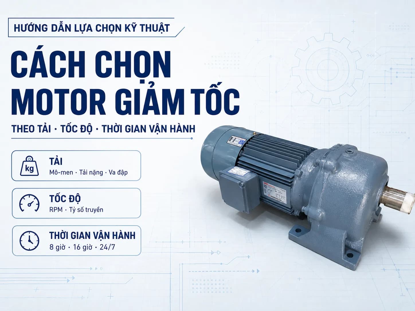
Selecting the correct geared motor cannot be based solely on the power rating indicated on the motor. A suitable drive system must simultaneously meet the actual load, starting torque, output speed, gear ratio, operating time, and mounting configuration on the machine.
If the power or torque is undersized, the motor is prone to overheating, overloading, and reduced gearbox lifespan. Conversely, excessive oversizing increases costs, dimensions, and power consumption. The following procedure helps engineers and machine builders determine critical parameters before selecting a geared motor.
1. Determine the Machine Load Type
Load is the first factor to check as it determines the torque, power, and service factor of the gearbox.
Uniform Load
A uniform load changes little during operation, has no significant shocks, and typically starts relatively smoothly.
Common applications:
Light-duty conveyors.
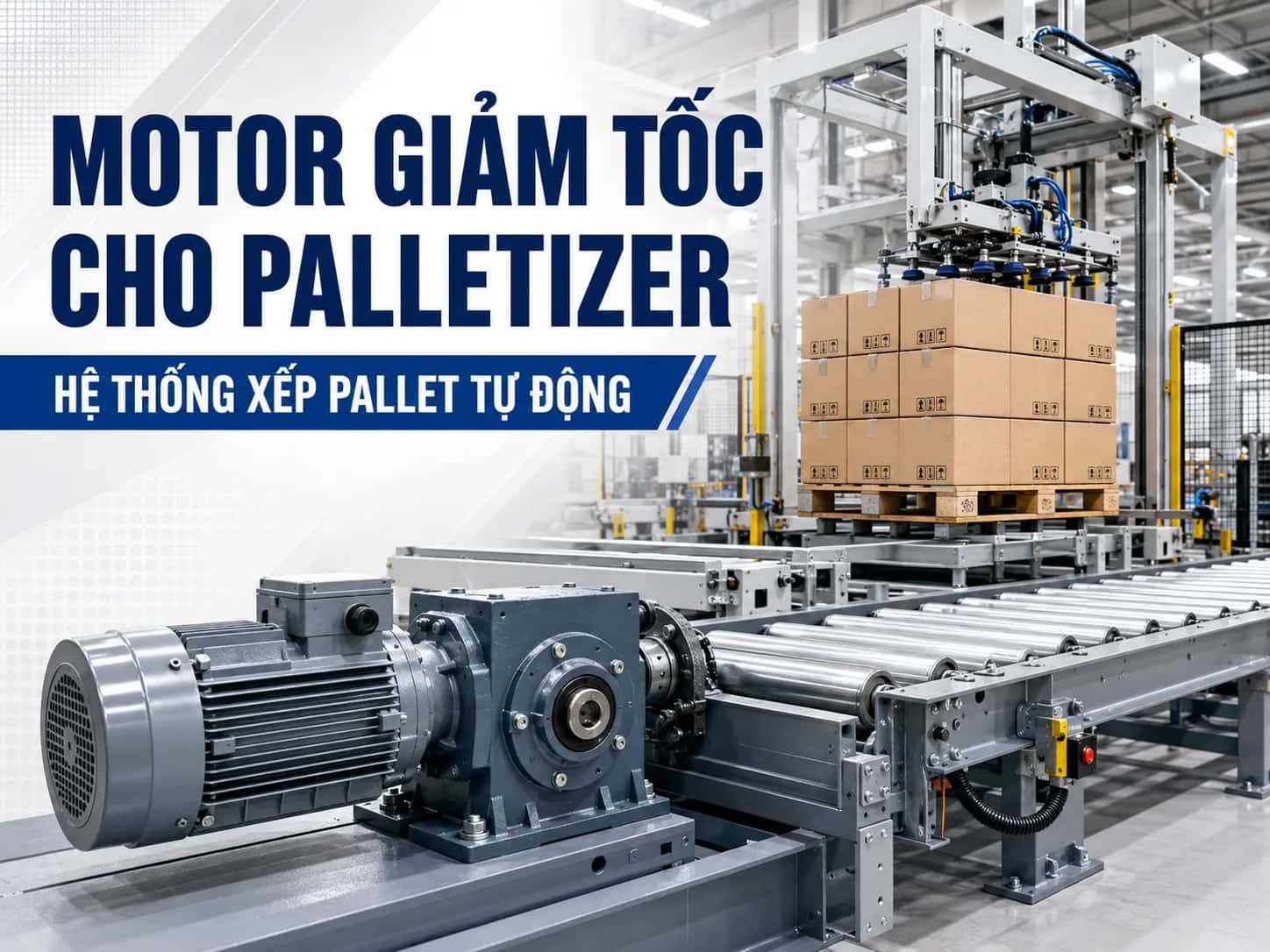
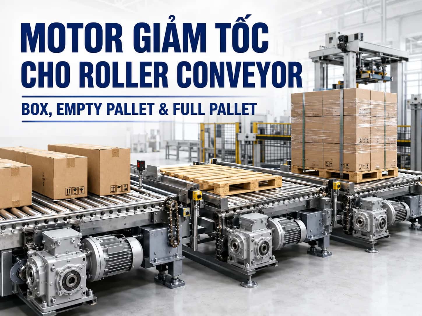
Roller conveyors.
Packaging machines.
Low-viscosity liquid agitators.
Continuously operating rotary mechanisms.
Variable or Heavy Load
Variable loads often occur when material mass, resistance, or working conditions are unstable.
Examples:
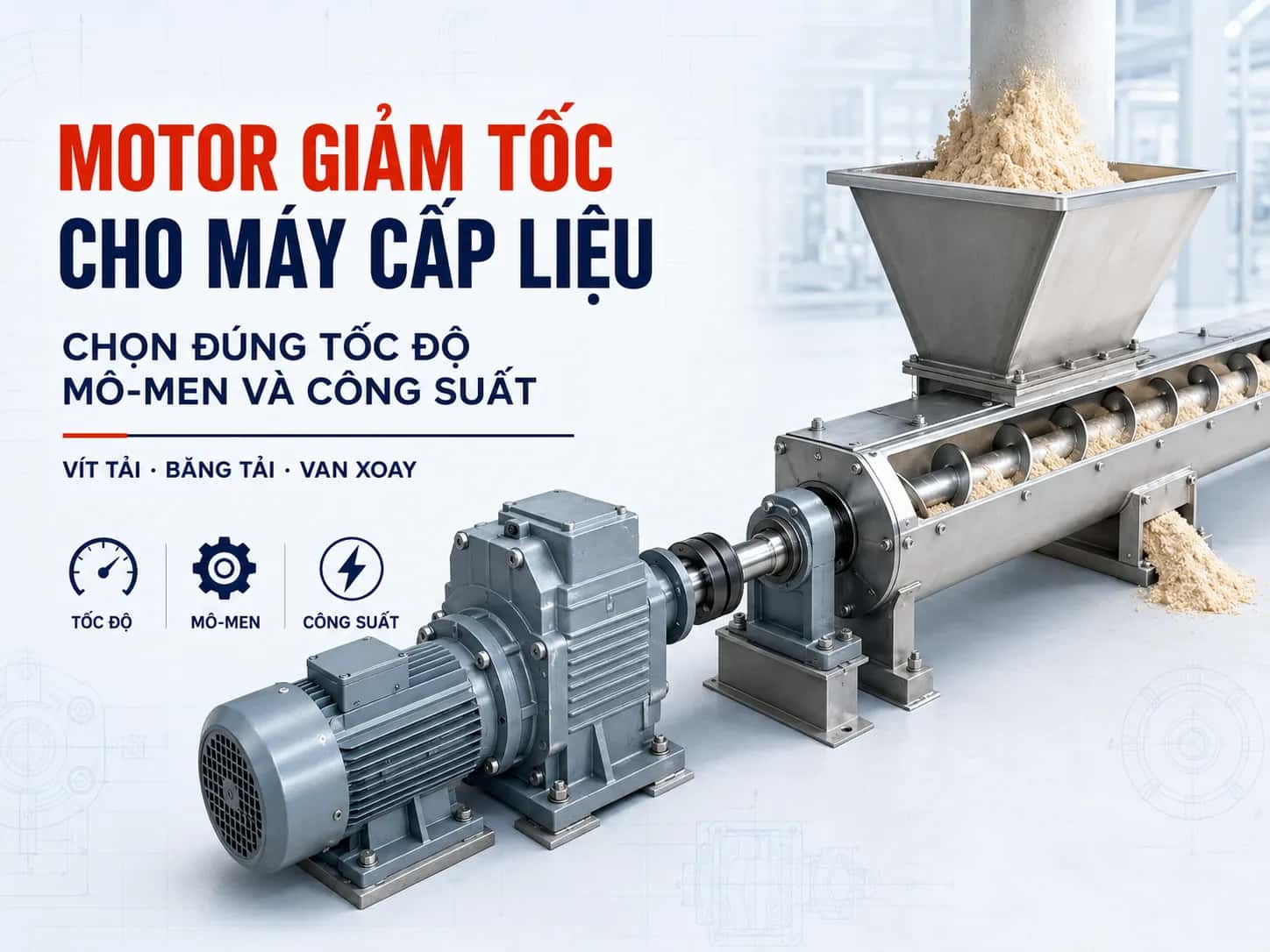
Screw conveyors with material.
Mixers.
High-viscosity liquid agitators.
Inclined conveyors.
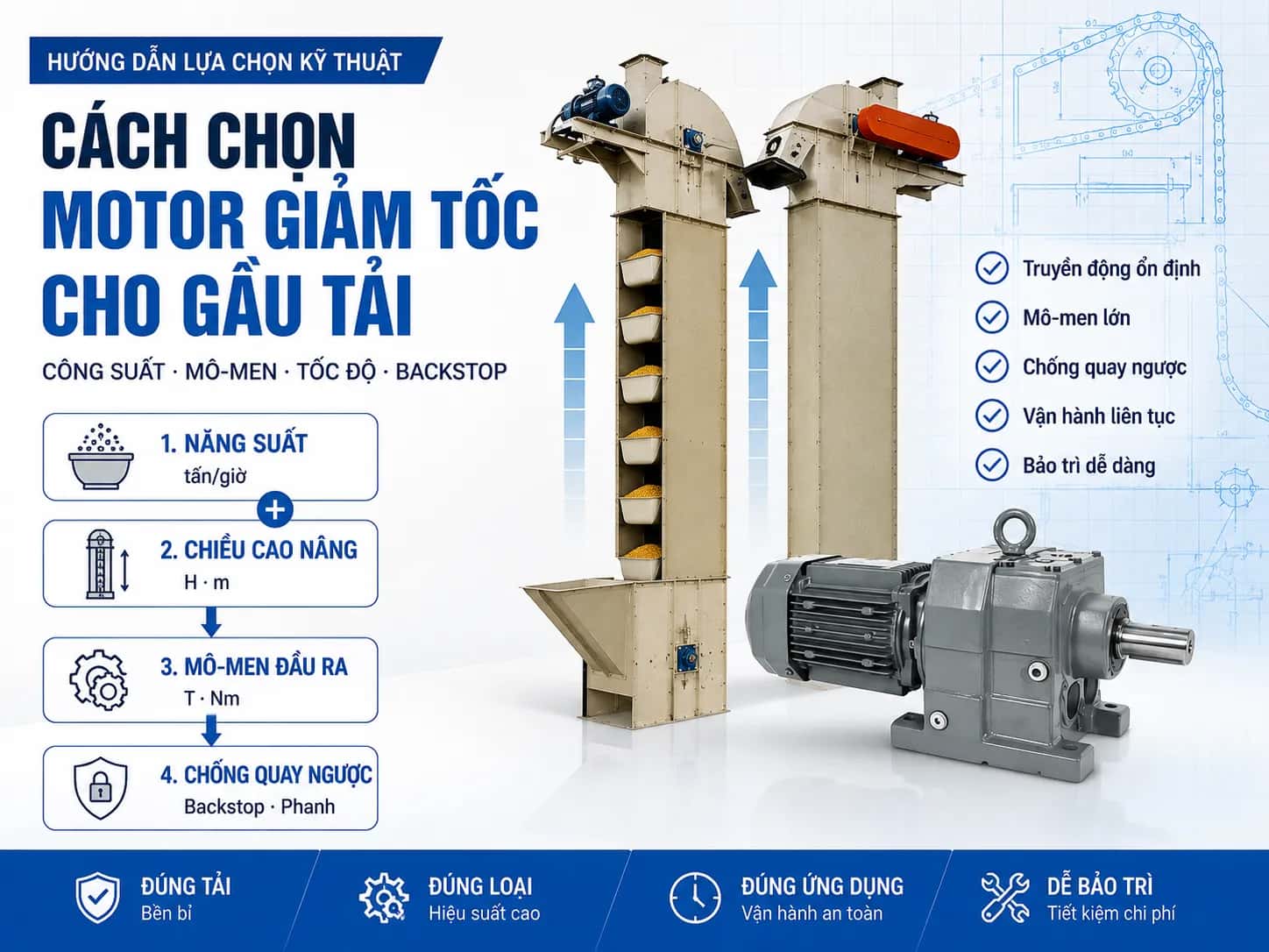
Bucket elevators.
Hoisting machines.
For these applications, it is necessary to check the operating torque and starting torque, rather than relying solely on the power of the motor currently in use.
Shock Load
Crushers, presses, reversing machines, or frequently starting mechanisms can create shock loads on shafts, bearings, and gears.
In such cases, it is necessary to select a gearbox with appropriate load-bearing capacity and refer to the service factor in the manufacturer's catalog.
Full-Load Starting
Conveyors, screw conveyors, or bucket elevators may need to start while still loaded. The starting torque in such cases is often much higher than when the machine is running at a steady state.
This is critical information when selecting geared motor power and starting methods.
2. Determine Output Speed and Gear Ratio
Output speed is the number of revolutions of the gearbox shaft per minute, usually measured in rpm.
The gear ratio is preliminarily determined by the formula:
i = n₁ / n₂
Where:
i: gear ratio.
n₁: motor input speed.
n₂: required output speed.
For example, a motor has a speed of approximately 1,450 rpm and the machine requires an output speed of 48 rpm:
i = 1,450 / 48 ≈ 30
A gearbox with a gear ratio close to 1/30 can be considered. However, the actual speed must be verified in the catalog as it depends on the motor's rated speed and the design of each transmission stage.
Do not simply provide the requirement for a “1/30 ratio gearbox.” When selecting, it is necessary to specify both the motor speed and the desired output speed.
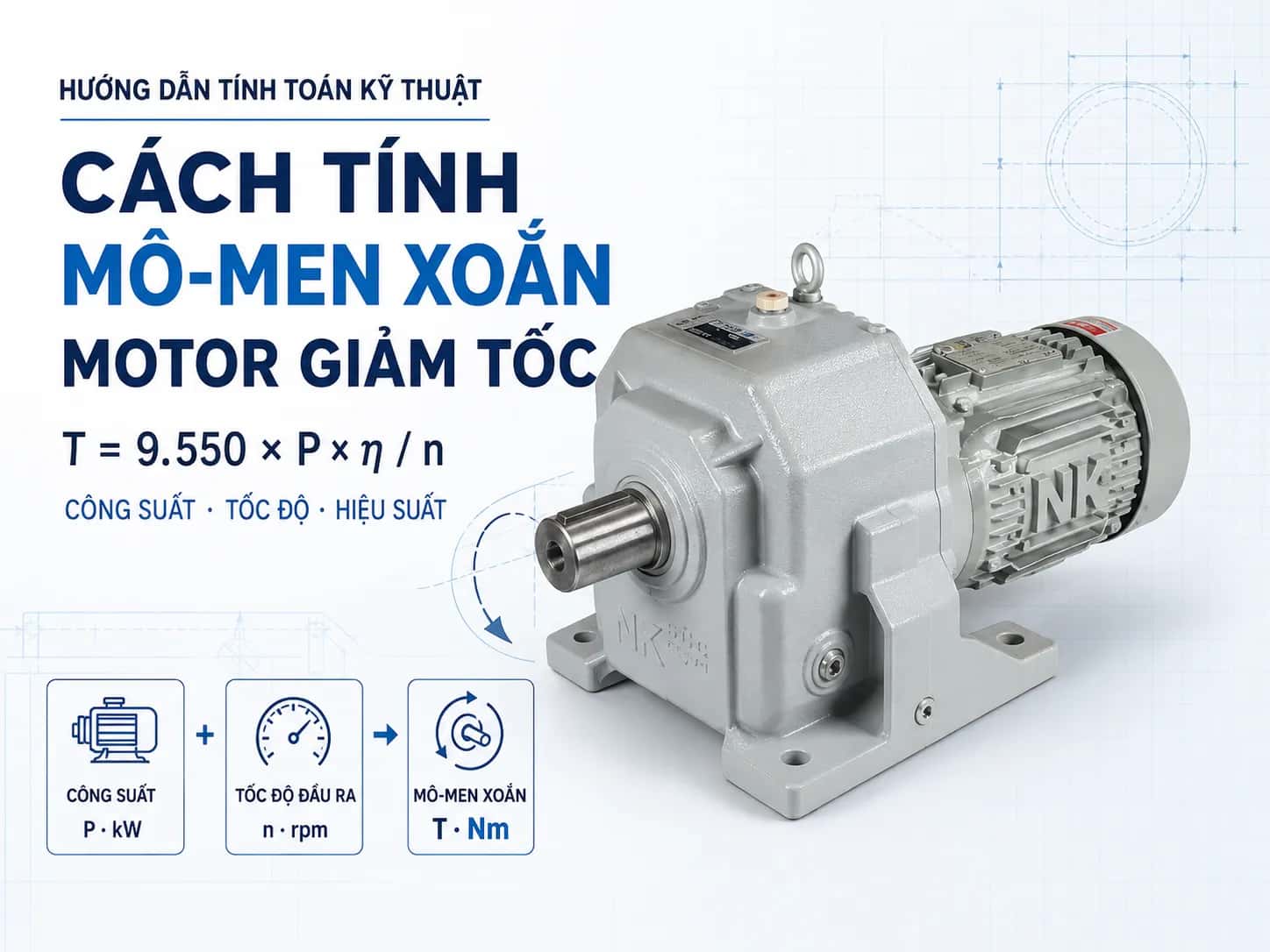
3. Calculating output torque
Torque represents the ability of a geared motor to pull, lift, or rotate a load.
It can be calculated approximately using the following formula:
T = 9,550 × P × η / n
Where:
T: output torque, in Nm.
P: motor power, in kW.
η: total efficiency of the transmission.
n: output speed, in rpm.
For example, for a 1.5 kW motor, an output speed of 50 rpm, and an assumed efficiency of 0.9:
T = 9,550 × 1.5 × 0.9 / 50 ≈ 258 Nm
The above result is for preliminary selection only. When finalizing the model, it is necessary to cross-reference the rated torque, service factor, radial load, and axial load in the manufacturer's catalog.
Do not assume efficiency values without first determining the type of gearbox and the number of transmission stages.
4. Checking starting torque
The torque required when the machine starts running is usually higher than the torque in a steady state.
This is particularly important for:
Conveyors loaded with goods.
Screw conveyors containing material.
Heavy-duty mixers.
Hoists and bucket elevators.
Mechanisms equipped with brakes.
Machines with frequent starts.
Before selection, it is necessary to determine:
Whether the machine starts under load or no-load conditions.
Required acceleration time.
Number of starts per hour.
Whether frequent reversing is required.
Whether a VFD is used.
A VFD can assist with soft starting and torque control, but it does not replace the need to select the correct power and gear ratio.
5. Selecting a geared motor based on operating time
Operating time directly affects motor temperature, lubricating oil, bearings, and gearbox service life.
Running less than 8 hours per day
With stable loads and a low number of starts, operating requirements are generally lighter. However, load torque and environmental conditions must still be checked.
Running from 8 to 16 hours per day
Attention should be paid to heat dissipation capacity, actual load levels, and lubrication mode. The motor should not frequently operate near its limits in hot environments or areas with poor ventilation.
Continuous 24/7 operation
Geared motors running continuously must be selected according to the manufacturer's specified service factor. Additionally, ambient temperature, oil change intervals, motor efficiency class, and maintenance requirements must be verified.
Intermittent operation with frequent starts
Operating time may be short, but repeated starting currents and impact loads can still cause the motor to overheat. In this case, the number of starts per hour is just as important as the total operating time.
6. Service factor and power reserve
The service factor reflects the severity of operating conditions compared to the rated load.
This value typically depends on:
Load type.
Operating hours per day.
Number of starts.
Impact/shock level.
Reversing frequency.
Ambient temperature.
Transmission method.
It is not advisable to apply a general rule such as always selecting a motor 20% or 30% larger. The safety margin must be based on the actual load and the selection table of each manufacturer.
Oversizing the power capacity can also increase costs, base plate dimensions, and system current.
7. Checking radial and axial loads
In addition to torque, the output shaft may also be subjected to radial and axial forces.
Radial load
Radial loads typically occur when the output shaft is fitted with:
Sprockets.
Pulleys.
Gears.
Conveyor drums.
The further the force is applied from the shaft shoulder, the greater the load on the shaft and bearings. Therefore, it is necessary to check the mounting position of the sprocket or pulley, not just the shaft diameter.
Axial load
Axial load is the pulling or pushing force along the axis. This type of load can occur in screw conveyors, agitators, or direct drive mechanisms.
The permissible load value must be verified according to the catalog of the specific model.
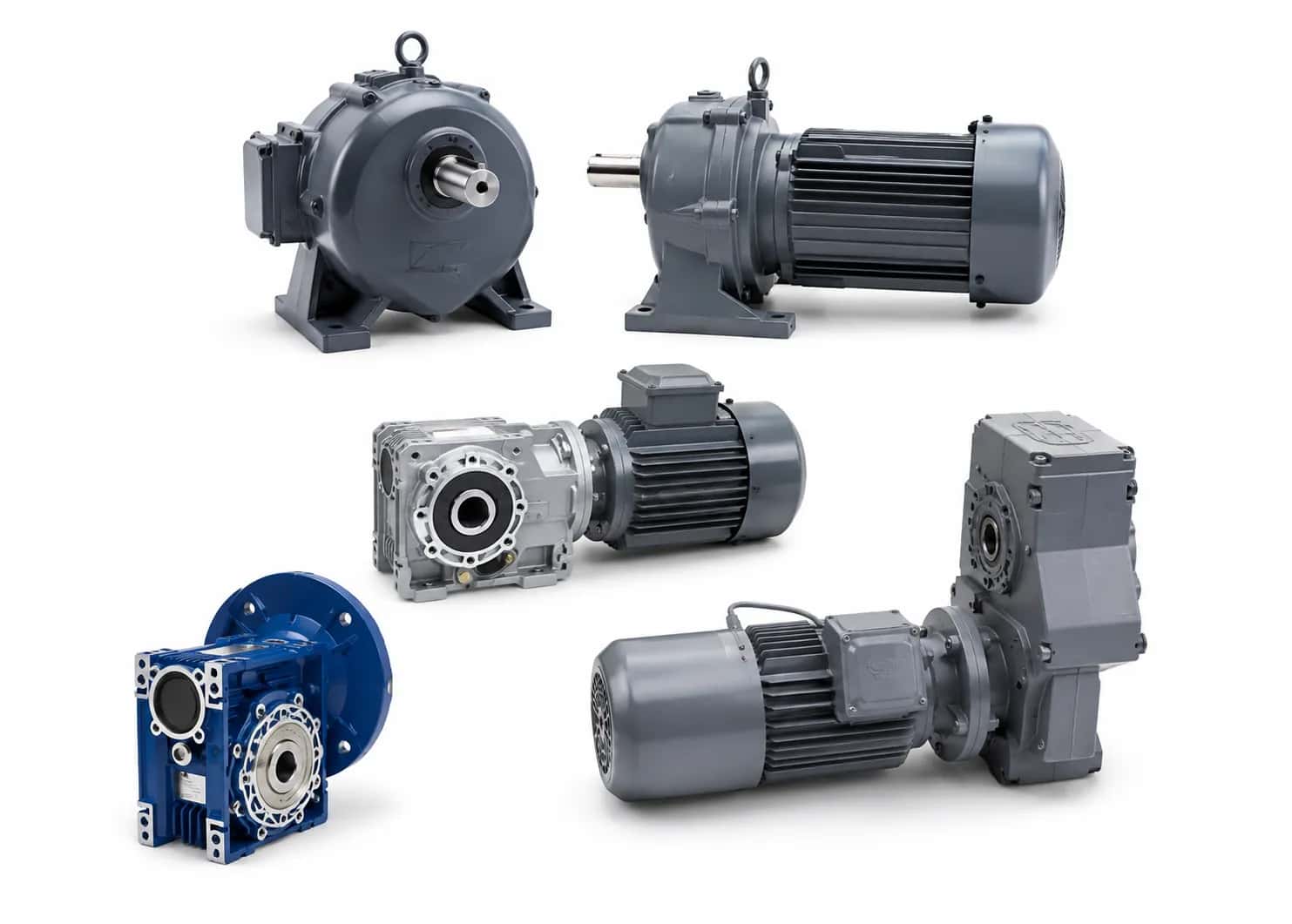
8. Selecting the appropriate gearbox type
Gearbox type | Main characteristics | Suitable applications |
|---|---|---|
Coaxial helical gear | High efficiency, common design | Conveyors, packaging machines, agitators |
Parallel shaft | Compact horizontal design, good torque | Conveyors, bucket elevators, screw conveyors |
Bevel helical gear | Right-angle transmission, high efficiency | Heavy-duty conveyors, mixers |
Worm gear | Compact design, high gear ratio | Small machines, adjustment mechanisms |
Cycloidal | Good shock resistance and heavy load capacity | Agitators, mixers, industrial equipment |
Planetary | High torque in a compact size | Heavy-duty machinery, precision equipment |
There is no single type of gear reducer that is best for every application. Selection must be based on load, installation space, efficiency, shaft orientation, and maintenance requirements.
9. Selecting the Mounting Type
Geared motors can be used in various configurations:
Foot-mounted.
Flange-mounted.
Horizontal mounting.
Vertical mounting.
Solid shaft.
Hollow shaft.
The foot-mounted style is suitable for machines with a base and is generally convenient for alignment or maintenance. The flange-mounted style is suitable when direct mounting to the machine frame is required or for compact designs.
Solid shafts typically transmit power via couplings, sprockets, or pulleys. Hollow shafts can be mounted directly onto the machine shaft, but it is necessary to verify the diameter, keyway, anti-rotation method, and applied forces.
When replacing a unit from a different manufacturer, you must compare the drawings of the foot, flange, shaft center height, and output dimensions before placing an order.
See more: What Are the Differences Between Foot-Mounted and Flange-Mounted Geared Motors?
10. Geared Motors Using VFDs
A VFD (Variable Frequency Drive) helps adjust speed, provide soft starting, and limit mechanical shock. However, note the following:
Running a motor at low speeds for extended periods may result in poor cooling due to slow fan rotation.
Increasing the frequency increases the mechanical speed of the motor and the gear reducer.
Torque at low speeds depends on the VFD control mode.
A VFD should not be used to compensate for an incorrectly selected gear ratio.
An independent cooling fan may be required if the motor runs at low speeds continuously.
The allowable frequency range must be confirmed according to the motor and gear reducer documentation.
11. Information Table Required When Selecting a Geared Motor
Information | Content to be determined |
|---|---|
Application | Conveyor, screw conveyor, agitator, hoist, etc. |
Load | Mass, pulling force, or torque |
Output speed | Required RPM |
Drum or lever arm | Drum diameter, force application radius |
Operating time | Hours per day |
Starting | Starts per hour, loaded or unloaded |
Drive type | Direct, coupling, chain drive, pulley |
Mounting position | Horizontal, vertical, foot or flange |
Power supply | Voltage, frequency, number of phases |
VFD | Yes or no, speed range |
Electromagnetic brake | Whether load holding is required |
Environment | Indoor, outdoor, dusty, humid, chemical exposure |
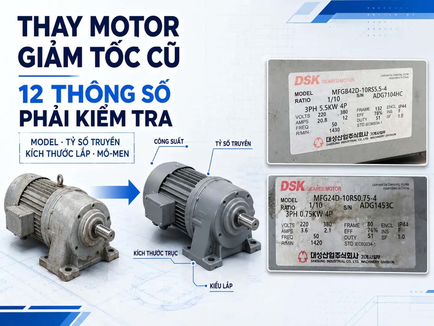
If you need to replace an old motor, please provide photos of the nameplate, drawings, shaft dimensions, and images of the mounting position on the machine.
See more: DSK - MFG Series Geared Motor
12. Example of selecting a geared motor for a conveyor
Suppose a conveyor requires an output speed of 40 rpm, operates 16 hours per day, starts under load, is driven by a chain sprocket, and uses a VFD.
The selection process should be carried out as follows:
Calculate the conveyor pulling force based on load mass, friction, and inclination angle.
Determine the torque on the pulley based on the pulling force and pulley radius.
Calculate the required power from torque and speed.
Select the gear ratio based on motor speed and output speed.
Check the starting torque when the conveyor is loaded.
Apply the service factor based on operating hours.
Check the radial load caused by the chain sprocket.
Select the mounting type suitable for the conveyor frame.
Check the speed range and cooling capacity when using a VFD.
Without sufficient data on pulling force, pulley diameter, and load conditions, do not conclude on a specific model based solely on the output speed.
Common mistakes when selecting a geared motor
Selecting only based on the old motor's power.
Failing to calculate starting torque.
Failing to check radial load.
Selecting a gear ratio without verifying the actual speed.
Ignoring the number of operating hours per day.
Overlooking the frequency of starts and reversals.
Selecting the wrong foot mount, flange, or mounting orientation.
Running the VFD too slowly or too quickly for extended periods.
Not cross-referencing drawings before machining the machine base.
Conclusion
The correct method for selecting a geared motor must begin with three factors: load, speed, and operating time. The load determines torque and power; the speed determines the gear ratio; and the operating time affects the service factor, heat dissipation, and equipment lifespan.
MDriveTech supports the selection of geared motors based on load, speed, operating time, and machine structure. Customers can send load parameters, machine photos, drawings, or photos of the equipment nameplate currently in use to receive verification and recommendations for a suitable model.
📞 Hotline: 0868 789 647
📧 Email: [email protected]
Frequently Asked Questions
How much larger should the gear motor be compared to the load?
There is no single safety factor that applies to all applications. The required safety margin depends on the load type, operating hours, number of starts, shock levels, and environmental conditions. It is recommended to calculate the actual torque and then refer to the service factor in the manufacturer's catalog.
Can a gear motor be selected based solely on power rating?
No. Two gear motors with the same power rating may differ in gear ratio, output torque, permissible load, shaft dimensions, and mounting type. Power rating is only one of the parameters that must be verified.
What should be considered for motors running continuously for 24 hours?
It is necessary to check the service factor, heat dissipation capacity, motor efficiency class, lubrication, and ambient temperature. Motors should not be operated near their limits frequently if cooling conditions or loads are unstable.
Can a smaller motor be selected when using a VFD?
This should not be assumed. While a VFD supports starting and speed control, the motor must still provide sufficient torque for the load. If the motor is undersized, the system may still become overloaded or fail to start.
How do I select a motor if the nameplate on the old equipment is missing?
You need to measure the output speed, shaft diameter, base or flange dimensions, and determine the load and operating current. It is recommended to send photos of the entire equipment and the mounting position for technical verification before selecting a replacement model.