What Are Radial and Axial Loads on a Gearbox?
Learn about radial and axial loads in gearboxes, their causes, how to calculate loads on sprockets and pulleys, and key considerations for gearbox selection.
What Are Gearbox Radial Load and Axial Load?
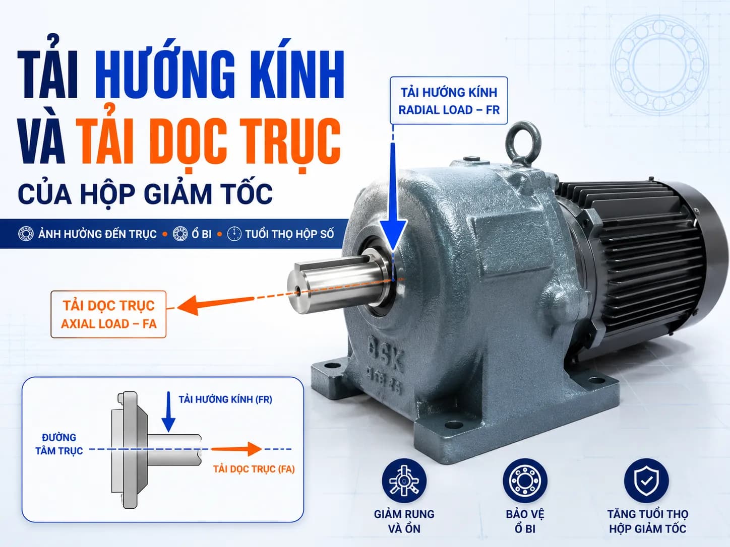
Gearbox radial load and axial load are two types of external forces acting directly on the output shaft. These are critical parameters to check alongside motor power, gear ratio, and torque when selecting a gearbox.
A gearbox may provide sufficient torque but still fail prematurely if sprockets, pulleys, drums, or load mechanisms generate forces exceeding the shaft and bearing load capacity. Common consequences include bearing overheating, vibration, increased backlash, oil leakage, or output shaft deformation.
What is gearbox radial load?
Gearbox radial load is the force acting perpendicular to the centerline of the output shaft. It is commonly denoted as FR.
Equivalent terms include:
Radial load
Overhung load
OHL
Radial force
Radial load typically occurs when the gearbox shaft is fitted with:
Sprockets
Belt pulleys
Gears
Drums
Wheels
Drive mechanisms mounted offset from the bearing position
For example, when a gearbox drives a conveyor via a sprocket, the chain tension acting on the sprocket creates a lateral force on the shaft. If this force is excessive, the shaft may bend, and the output bearings will be overloaded.
What is gearbox axial load?
Axial load is the force acting parallel to the shaft centerline. It is commonly denoted as FA.
Equivalent terms include:
Axial load
Thrust load
Axial force
Axial load can occur in:
Screw conveyors
Agitators generating thrust
Pressing or pushing mechanisms
Helical gears
Bevel gears
Tensioned or compressed shafts
Misaligned couplings in the axial direction
Axial force acts directly on the thrust bearings, shaft, and internal positioning components of the gearbox.
Comparison of radial load and axial load
Criteria | Radial load | Axial load |
|---|---|---|
Symbol | FR | FA |
Direction of action | Perpendicular to the shaft | Parallel to the shaft |
English term | Radial load, overhung load | Axial load, thrust load |
Source | Sprockets, pulleys, gears, drums | Screw conveyors, pulling/pushing forces, helical gears |
Affected components | Shaft, bearings, oil seals | Thrust bearings, shaft, positioning components |
Why is the mounting position of sprockets and pulleys critical?
Radial load depends not only on the magnitude of the force but also on the distance from the point of force application to the output bearing.
Basic relationship:
Bending moment = Radial load × Force application distance
The further the sprocket or pulley is from the shaft shoulder, the greater the bending moment. Therefore, for the same load, different mounting methods can significantly change the service life of the shaft and bearings.
When installing, you should:
Place the sprocket or pulley as close to the shaft shoulder as possible.
Do not let the hub protrude too far from the end of the shaft.
Tension belts and chains correctly.
Align concentrically before operation.
Do not hammer sprockets or pulleys onto the shaft.
Add an external support bearing when the shaft is long or the load is heavy.
How to estimate the force on a sprocket or pulley
The tangential force required to transmit torque can be estimated using the formula:
Ft = 2T / d
Where:
Ft: tangential force, in N
T: torque on the shaft, in Nm
d: pitch diameter, in m
If the diameter is entered in millimeters:
Ft = 2,000 × T / d
Example of calculating force on a sprocket
A gearbox has:
Output torque: 200 Nm
Pitch diameter of the sprocket: 200 mm
Tangential force:
Ft = 2,000 × 200 / 200 = 2,000 N
The value of 2,000 N is the tangential force required to transmit the torque. This is not necessarily the actual radial load acting on the bearing.
The actual load also depends on:
Tension on the tight and slack sides of the chain
Initial belt tension
Weight of the sprocket, pulley, or drum
Wrap angle
Number of sprocket teeth
Shock load
Distance from the point of force application to the shaft shoulder
After determining the actual load, it must be compared with the permissible load limit of the specific gearbox model.
Can radial load and axial load occur simultaneously?
Yes. In many mechanisms, the output shaft is simultaneously subjected to:
Torque
Radial load
Axial load
Bending moment
Shock load
Reversing load
When FR and FA occur simultaneously, the load-carrying capacity of the bearing may be lower than in cases where only one type of force is present.
A fixed ratio between radial load and axial load should not be applied to all gearboxes. Load-carrying capacity depends on:
Gearbox size
Shaft diameter
Type and size of bearings
Distance between bearings
Point of force application
Direction of tension or compression
Mounting position
Output speed
Operating time
Degree of shock and reversal
Signs that external load exceeds limits
When radial or axial loads are excessive, the gearbox may exhibit:
Abnormally hot bearings
Vibration at the shaft end
Humming or knocking noises
Deflection of the output shaft
Increased shaft end play
Eccentric oil seal operation
Oil leakage
Uneven gear wear
Reduced bearing service life
Shaft deformation or fracture
These phenomena are easily mistaken for insufficient lubrication or gear damage. However, the actual cause may stem from excessive external loads or drive components mounted too far from the shaft shoulder.
When is an external support bearing required?
Consider adding an external support bearing when:
Drums or pulleys have significant weight
Sprockets are positioned far from the shaft shoulder
The load shaft is long
Belts require high tension
Chains are subject to impact loads
The machine reverses frequently
The gearbox is directly supporting the entire load
The radial load exceeds the load-carrying capacity of the output bearings
An external support bearing helps transfer the force to the machine structure, reducing the direct load on the gearbox shaft and bearings.
The support bearing must be aligned concentrically with the shaft. If installed eccentrically, the support bearing may create additional load instead of reducing it.
How to reduce radial load on the gearbox
The following measures can be applied:
Increase the sprocket or pulley diameter when machine conditions permit.
Position drive components close to the shaft shoulder.
Adjust belt and chain tension to the correct level.
Use direct couplings where appropriate.
Install a separate support bearing for drums, pulleys, or long shafts.
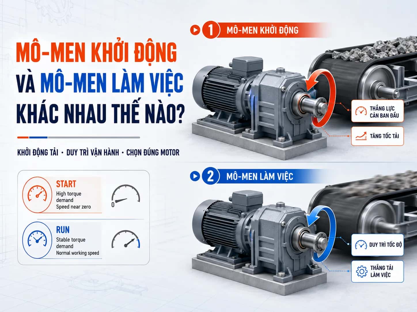
Reduce impact loads during startup.
Select a gearbox with larger shafts and bearings.
Check the concentricity between the gearbox and the machine shaft.
Do not allow the gearbox to bear the entire weight of the load mechanism.
Recalculate when changing sprocket or pulley diameters.
Information required for gearbox selection
To verify radial and axial loads, the following must be determined:
Motor power and speed
Gear ratio
Output speed
Load torque
Load type: uniform, impact, or reversing
Components mounted on the shaft
Sprocket, pulley, or gear diameter
Distance from the point of force application to the shaft shoulder
Belt or chain tension
Weight of the pulley or drum
Axial load in tension or compression
Foot-mounted or flange-mounted configuration
Daily operating hours
Number of starts or reversals
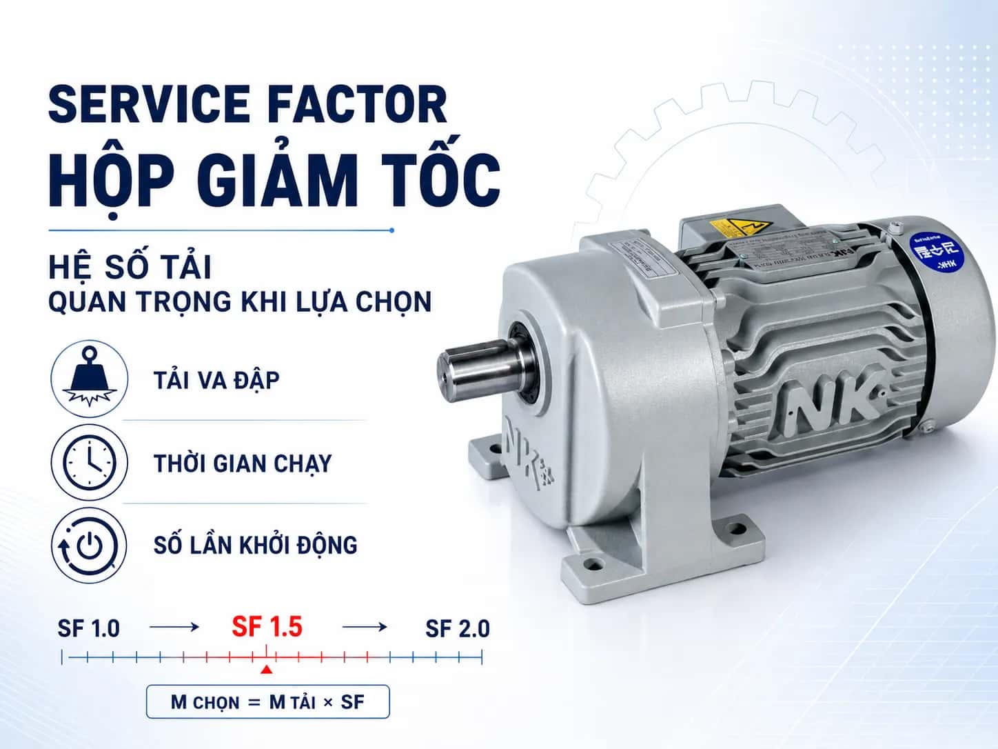
For DSK, Nara Samyang, or NK geared motors and gearboxes, selection must be based on the correct model, shaft dimensions, and actual installation conditions.
Frequently Asked Questions
Do sprockets create radial loads?
Yes. The chain tension acts on the sprocket and creates a force perpendicular to the gearbox output shaft.
Do belt pulleys affect gearbox bearings?
Yes. Excessive belt tension or pulleys installed too far from the shaft shoulder will increase radial loads and bending moments, causing bearings to overheat or wear out prematurely.
Do couplings create radial loads?
Properly aligned couplings typically generate minimal external loads. However, parallel misalignment, angular misalignment, or axial thrust can increase loads on the shaft and bearings.
Does increasing sprocket diameter help reduce load?
While maintaining the same torque, increasing the pitch diameter of the sprocket will reduce the required tangential force. However, it is still necessary to verify chain speed, installation dimensions, and the total load of the mechanism.
How much axial load can a gearbox withstand?
There is no universal value for all gearboxes. Load capacity depends on the model, shaft configuration, bearing design, mounting position, force direction, and operating conditions.
Is selecting a gearbox based solely on torque sufficient?
No. In addition to torque, it is necessary to check radial loads, axial loads, service factors, speed, force application points, and operating duty cycles.
MDriveTech gearbox selection consulting
MDriveTech provides support for selecting gear motors and gearboxes from DSK, Nara Samyang, and NK for:
Conveyors
Screw conveyors
Agitators
Packaging machines
Winch drums
Lifting equipment
Industrial drive systems
For accurate verification, customers should provide machine photos, motor nameplates, output speed, load torque, sprocket or pulley dimensions, and installation layout drawings.
Hotline: 0868 789 647
Email: [email protected]
Conclusion
Radial loads act perpendicular to the shaft, while axial loads act parallel to the shaft centerline. Both directly affect the bearings, shaft, oil seals, and the service life of the gearbox.
When selecting a gearbox, one should not only check power, gear ratio, and torque. It is essential to determine external loads, sprocket or pulley mounting positions, distance to the shaft shoulder, and actual operating conditions to select the correct model.