Installation, Operation, and Maintenance Guide for DSK Geared Motors
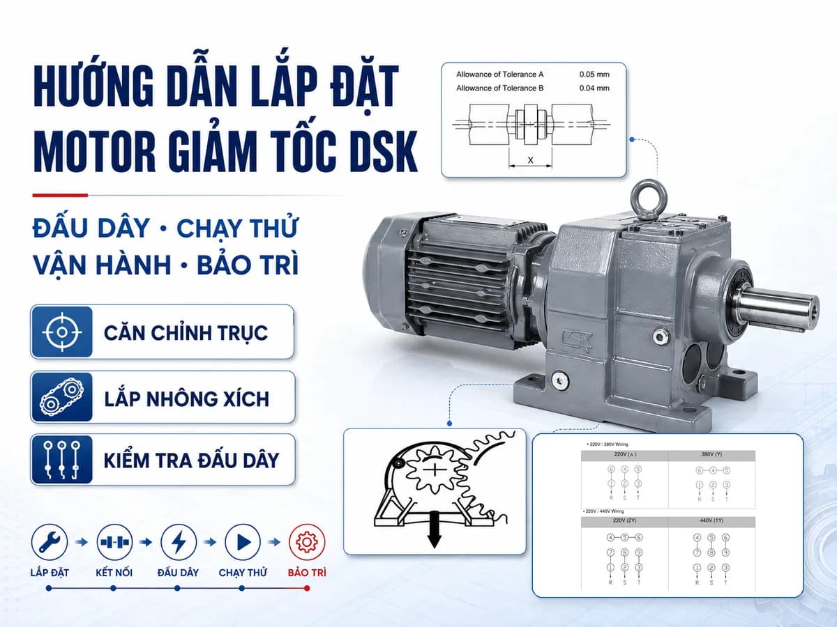
Proper technical installation of DSK geared motors, covering inspection, alignment, wiring, commissioning, maintenance, and common troubleshooting.
Installation, Operation, and Maintenance Manual for DSK Geared Motors
Proper installation of DSK geared motors is a critical requirement for stable equipment operation. Misalignment during installation, load connection, or wiring can lead to motor failure to start, overheating, vibration, abnormal noise, grease leakage, or damage to gears, bearings, and seals.
The following instructions are compiled in accordance with the sequence in the DSK Geared Motor – Instruction Manual, covering everything from inspection upon receipt to installation, commissioning, maintenance, and troubleshooting.
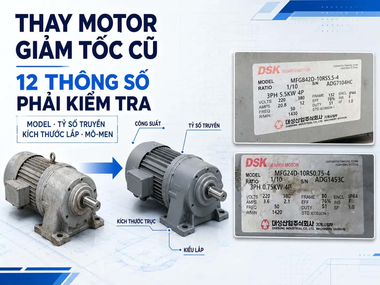
Inspecting DSK geared motors upon receipt
After unboxing, verify the product against the order information before proceeding with installation.
Initial inspection checklist
Correct geared motor model.
Correct gear ratio.
Correct motor power.
Correct voltage and frequency.
No dents, cracks, or impact damage from shipping.
No moisture, dust accumulation, or contamination.
Bolts, screws, and nuts are not loose.
Load conditions match the configured specifications.
Starting frequency and duty cycle meet the original requirements.
Do not install the equipment if the parameters on the nameplate do not match the purchase order. Using the incorrect gear ratio, voltage, or power can cause damage to both the geared motor and the driven machine.
Safe transportation of geared motors
When lifting or moving a geared motor, do not stand or walk under suspended equipment. Products falling during lifting can cause serious injury.
If the geared motor is equipped with an eye bolt or eye plate, check its integrity before use. Once the geared motor has been installed into the machine, do not use the motor's own eye bolt to lift the entire system.
During transportation, avoid dropping, impacting, or subjecting the equipment to abnormal forces. This document does not provide specific lifting load capacities; use lifting equipment appropriate for the actual weight of the product.
Installation conditions for DSK geared motors
The installation conditions specified in the document include:
Item | Requirement |
|---|---|
Ambient temperature | -10°C to 40°C |
Humidity | Maximum 85% |
Altitude | Maximum 1,000 m above sea level |
Location | Indoors, well-ventilated |
Vibration | Reduced to below 0.5G |
Surface flatness | Below 0.2 mm |
Fixing | Using four bolts |
Do not place any obstructions around the motor fan or cooling air path. Blocked airflow may cause abnormal temperature increases.
The mounting surface must be flat, rigid, and have minimal vibration. An uneven mounting surface can cause the gear motor assembly to vibrate, misalign, and loosen bolts during operation.
This document describes products that use grease lubrication and can be mounted in various orientations. This content should not be applied to all DSK series; please refer to the catalog or technical documentation of the specific model before application.
Hazard Warning
Standard motors must not be used in areas with flammable or explosive gases. For applications in hazardous environments, the documentation requires the use of motors with appropriate explosion-proof configurations.
Connecting the gear motor to equipment
Direct connection via coupling
When connecting the gear motor shaft directly to the machine shaft, it is recommended to use a flexible coupling and precisely align both shaft ends.
The specified tolerances are:
Tolerance A: 0.05 mm.
Tolerance B: 0.04 mm.
Tolerance X: as specified by the coupling manufacturer.
Concentric or angular misalignment can increase vibration and loads on the shaft and bearings. After alignment, ensure that the coupling bolts are tightened securely.

Installing sprockets, pulleys, and gears
When using sprockets, pulleys, or gears on the output shaft, the following requirements must be met:
The centerlines of the two shafts must be parallel.
The tension of the chain or belt must be perpendicular to the shaft centerline.
The diameter of the sprocket or gear should be at least three times the diameter of the output shaft.
Do not overtighten the belt.
Do not leave the chain too slack.
Sprockets or pulleys should be positioned close to the gearbox face.
The radial load must be within the allowable limits of the model.
Common mechanical installation errors
Installation Error | Impact | Inspection Method |
|---|---|---|
Misaligned coupling | Increased vibration and bearing load | Re-align both shaft ends |
Non-parallel shafts | Chain or belt misalignment | Check center and parallelism |
Excessive chain slack | Creates impact load during startup | Adjust slack |
Overtightened belt | Increased load on shaft and bearings | Reduce tension |
Sprocket placed far from gearbox face | Increased radial load | Move sprocket closer to gearbox face |
Loose base bolts | Causes significant vibration | Retighten and check mounting surface |

Checking the rotation direction of DSK gear motors
For the power range of 0.2–7.5 kW specified in this document:
Reduction ratio | Number of reduction stages | Rotation direction relationship |
|---|---|---|
1/5 to 1/20 | Two stages | Input and output shafts rotate in the same direction |
1/25 to 1/200 | Three stages | Input and output shafts rotate in opposite directions |
The above information applies only to the scope of this document. For other series or configurations, refer to the catalog or technical documentation of the specific model before application.
Before connecting to the machine, it is recommended to run the motor without load for 1–2 seconds to verify the rotation direction. For three-phase motors, the direction can be reversed by swapping any two of the three phases R, S, and T.
Only reverse the direction after the motor has come to a complete stop. Reversing while the shaft is still rotating may cause equipment damage.
Wiring DSK gear motors
General wiring requirements
Use the correct voltage and frequency as specified on the motor nameplate.
Connect the grounding terminal.
Install an overload protection relay.
Use appropriate fuses, breakers, and switching devices.
Keep the voltage drop on the cables within 2%.
Do not pull, bend, or crush the wires excessively.
Do not operate while the terminal box cover is open.
If the wiring diagram on the motor nameplate differs from the one in this document, the diagram on the product must take precedence, and you should contact the technical department for verification.
Safety warnings
The power supply must be completely disconnected before wiring, repairing, or inspecting terminals. Do not touch terminals while energized.
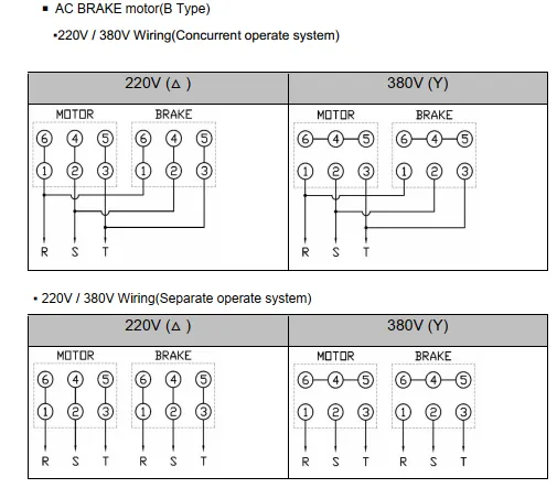
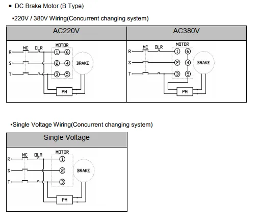
Wiring brake-equipped gear motors
This document provides separate diagrams for:
Motors using AC brakes.
Motors using DC brakes.
Brakes operating simultaneously with the motor.
Brakes with independent power supply and control.
For DC brake configurations, the system may use a DC power supply according to the product diagram. Do not modify the diagram without correctly identifying the brake configuration.
When using a VFD, the brake power supply must be bypassed from the VFD according to the instructions in this document. The output voltage from the VFD may cause the brake to malfunction.
Do not allow water, oil, or grease to enter the brake unit. For hoisting mechanisms, an independent fall-prevention device is required, and the brake must not be released manually while the system is under load.
Hazard Warning
Do not operate hoisting equipment if the brake has not been inspected. Do not release the brake manually while a load is suspended or being lifted.
Notes on VFD operation
When using a VFD, the documentation notes the following:
Motor temperature may increase.
Noise and vibration levels may increase.
Running at low speeds reduces the cooling efficiency of the fan.
The brake power supply should not be routed through the VFD output.
For 400 V rated motors, verify the surge voltage with the VFD supplier.
The documentation does not specify a minimum operating frequency. Refer to the catalog or technical documentation for the specific model before implementation.
Geared motor commissioning procedure
Follow this sequence:
Check cables and terminals.
Check couplings, sprockets, or belts.
Check fuses and breakers.
Check thermal overload relays.
Check grounding.
Run without load for 1–2 seconds to confirm the direction of rotation.
Perform a no-load test run.
Gradually increase the load to the operating load.
Do not apply full load during the initial startup. If incorrect rotation, vibration, or abnormal noise occurs, stop the machine and inspect.
Hazard Warning
Do not approach the shaft or rotating components. Rotating parts must be equipped with appropriate protective guards.
Geared motor inspection during operation
Item | Requirement |
|---|---|
Current | Do not exceed the value on the nameplate |
Noise | No abnormal sounds |
Vibration | No abnormal vibration at the motor and gearbox |
Surface temperature | Do not exceed 80°C as per documentation |
Leakage | No grease leakage at seals, brackets, or mating surfaces |
Do not touch the surface of the operating gear motor directly, as the temperature can cause burns. If any abnormal noise, vibration, overheating, or speed reduction occurs, stop the machine immediately for inspection.
In the event of a power failure, turn off the power switch to prevent the machine from restarting automatically when power is restored.
DSK Gear Motor Inspection and Maintenance Schedule
Inspection every 2–3 days
Load current.
Noise.
Vibration.
Surface temperature.
Grease leakage at seals and joints.
Inspection every 6 months
Based on an 8-hour/day operating condition:
Item | Inspection Content |
|---|---|
Mounting bolts | Check for looseness and retighten |
Chains, belts | Check and adjust tension |
Insulation resistance | Greater than 1 MΩ when measured with a 500 V source |
Brake gap | Check within permissible limits |
Inspection and adjustment of the brake gap should be performed by qualified personnel.
Lubricating grease and seals
The gear motor is pre-filled with lubricating grease at the factory and generally does not require frequent replenishment.
Replacing the grease after approximately 10,000 hours can help extend service life. This is not a mandatory cycle for all applications; load conditions, temperature, and operating time may affect the maintenance timing.
Seal life depends on usage conditions. Replacement of grease, seals, or O-rings should be performed by a technical service provider.
Gear Motor Troubleshooting Table
Symptom | Probable Cause | Initial Inspection Action |
|---|---|---|
Motor does not rotate | Power loss, broken wire, faulty contact | Check power supply and circuit |
Cannot pull load | Excessive load, phase loss | Reduce load, check voltage and phases |
Abnormal noise | Foreign object, damaged bearing or gear | Stop machine and contact technical support |
Overload relay tripped | Incorrect setting or overload | Check settings and load |
Fuse blown, breaker tripped | Under-rated protection device or overload | Check and reselect |
Overheating | Overload, incorrect voltage, blocked air path | Reduce load, check power, and clean |
Sudden speed drop | Voltage drop, overload, gear wear | Check power supply and load |
High vibration | Incorrect installation, loose bolts | Retighten, check flatness |
Grease leakage | Loose bolts, damaged seal, excessive grease | Retighten or contact technical support |
Brake not working | Incorrect wiring | Check wiring diagram |
Long braking time | Oil on friction disc, high inertia load | Stop machine, reduce load, and contact technical support |
Brake motor overheating | High braking frequency, heavy load | Reduce frequency and load |
Do not disassemble gears, bearings, windings, or brake units yourself. Internal damage must be inspected by a qualified technician.
Pre-commissioning checklist for gear motors
Correct model.
Correct gear ratio.
Correct voltage.
Correct frequency.
Flat mounting surface.
Bolts are tightened.
Shafts are aligned.
Chain or belt has proper tension.
Wiring and grounding are correct.
Rotation direction has been checked.
Important safety warnings
Disconnect power before wiring, repairing, or inspecting.
Do not touch rotating shafts or components.
Do not operate with the terminal box cover open.
Do not touch the surface of the gear motor while it is hot.
Do not stand under equipment being lifted.
Do not use the motor's eye bolt to lift the entire machine.
Do not manually release the brake while the mechanism is under load.
Stop the machine immediately if unusual noise, vibration, or temperature is detected.
Disassembly, repair, or replacement of internal components must be performed by a qualified technician.
Conclusion
Proper installation of the DSK gear motor helps minimize vibration, overheating, and unnecessary loads on shafts, bearings, and transmission components. Before full-load operation, check the power supply, rotation direction, alignment, chain or belt tension, and perform a no-load test run.
During operation, periodically monitor current, noise, vibration, temperature, and grease leakage. Do not attempt to disassemble or repair gears, bearings, windings, or brake units without sufficient expertise.
MDriveTech provides support for checking models, rotation directions, wiring diagrams, and installation conditions for DSK gear motors according to specific practical applications.
Hotline: 0868 789 647
Email: [email protected]